
Design of High-resolution Long-wave Infrared Continuous Zoom Optical System
An infrared thermal imaging camera is a photoelectric instrument for people to monitor, track and identify long-distance targets at night and in bad weather. It has been widely used in all-weather monitoring fields such as national defense, fire prevention and disaster relief, and geological exploration in recent years. It has significant economic and social benefits. Infrared thermal imaging cameras have three main forms: single field of view, dual field of view, and continuous zoom.
The single-field infrared thermal imaging camera has a single fixed focal length, and the field of view is small, which cannot meet the needs of target search and identification at the same time; the dual-field thermal imaging camera has two different focal lengths, forming two large and small fields of view, which can be used large field of view search, small field of view to identify targets.
There have been several domestic research results on high-zoom long-wave infrared continuous zoom systems. Cooled detectors are used, such as ten times designed by Zhang Liang et al., 20 times designed by Chen Luji et al., and 25 times long-wave infrared continuous zoom system designed by Jia Xingrui. Zoom optical system; using uncooled detectors, such as the 10x designed by Liu Feng and the 4× long-wave infrared continuous zoom optical system designed by Bai Yu.
Foreign research results include the 2010 American Mark C. An infrared zoom optical system with a 30× zoom ratio reported by Sanson et al. However, due to the development of detectors, there are few publications on high-resolution infrared zoom systems. This article makes a new design attempt at this point.
The design of the infrared continuous zoom optical system requires that the focal length change within a certain range and the image plane position is fixed, the relative aperture of the system is large and remains almost unchanged during zooming, and it requires good imaging quality for each focal length and field of view. Therefore, there is a certain technical complexity in the design, manufacture, and assembly.
Based on the design requirements of actual products, this paper designs a 6× continuous zoom infrared optical system with a focal length of 20~120mm based on the design theory of a continuous zoom optical system. When the focal length of the system is 20~90mm, the F-number is 1, and when the focal length is 90~120mm, the F-number is 1.1.
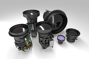
Compared with previous designs, this system has a higher optical resolution and is suitable for vanadium oxide 640×512 element uncooled detectors. The pixel size is only 17μm×17μm. It adopts a mechanically compensated zoom structure and uses five pieces of germanium single crystal lens and one piece of the chalcogenide glass lens.
On the premise of ensuring a higher zoom ratio and a large aperture, the resolution of the system is improved, and lower-priced detectors and optical materials are used, which can effectively control the overall cost while meeting the requirements of use, and has good practicality performance.
1. Design example
1.1 Design principle
This design adopts a positive group mechanical compensation structure (that is, the compensation group has a positive optical power). The lens diameter is small, the focal length of the front fixed group is longer, and the secondary spectrum is small.
Two-component motions are used to achieve zooming and compensation, and the number of motion components is small, which is convenient for the design and optimization of the structure. The optical zoom system can be divided into the 1-front fixed group; 2-variable magnification group; 3-compensation group; 4-rear fixed group; contributions to the overall optical power are 1-positive; 2-negative; 3 -Positive; 4-Positive.
When the zoom group moves linearly to change the position, the focal length of the system and the position of the image plane also change accordingly. To ensure the stability of the image plane, the cam mechanism needs to drive the compensation group to perform the nonlinear movement to compensate for the image plane position. The zoom principle is shown in Figure 1.
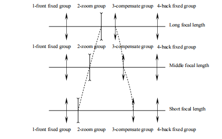
Fig.1 Sketch map of zoom optic system
The design process of the system is divided into two stages: obtaining a Gaussian solution and aberration design. First, determine the focal length, lens interval, moving range of the zoom group and compensation group of each lens in the system according to the parameters such as the focal length range, relative aperture, image size and shape size required by the system; and then calculate it according to the Gaussian solution data ZEMAX software is used to calculate the aberration and optimize the design of the initial structure parameters of the lens.
In the design, it is necessary to select multiple different focal length positions according to the same proportion of the entire focal length change range. When the system is at the above focal length position, use the front fixed group, zoom group, and compensation group to optimize the aberration to the minimum, and then use the rear fixed group to correct the residual image.
1.2 Design index
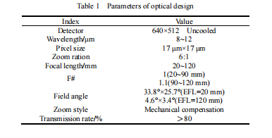
This design uses a vanadium oxide 640×512 element uncooled long-wave infrared detector with a pixel size of 17μm×17μm. According to actual application requirements, the main design indicators of the infrared continuous zoom optical system are shown in Table 1.
1.3 Design results
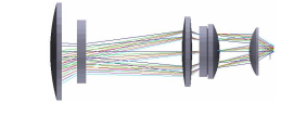
The shape and structure of the infrared continuous zoom optical system designed according to the index is shown in Figure 2. Figure 2(a), Figure 2(b), and Figure 2(c) show the appearance and structure of the system when the short focal length is 20mm, the medium focal length is 60mm, and the long focal length is 120mm. The total length of the system is 264mm.
(a) Layout of zoom optic system when EFL=20mm
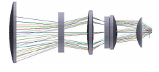
(a) Layout of zoom optic system when EFL=60mm
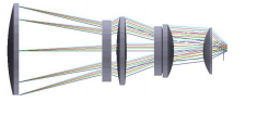
(a) Layout of zoom optic system when EFL=-120mm
Fig.2 Layout of LWIR continuous zoom optic system
The zoom ratio of the system is 6×, and the optimized design is carried out using ZEMAX optical-aided design software. It adopts the structure of 4 groups of 6 elements, the front fixed group is a positive power single lens, which reduces the weight of the system. The second lens is a negative lens of the variable magnification group, the third is a positive lens of the compensation group, and the rear fixed group uses 3 separate lenses, which can effectively optimize the remaining aberration of the previous structure.
In terms of materials, since germanium single crystals have a high refractive index and low dispersion for 8~12μm long-wave infrared light waves, 5 germanium single crystal lenses and 1 chalcogenide glass lens are used to eliminate chromatic aberration. The number of lenses is small and the price is relatively low (the price of chalcogenide glass is only one-third of that of zinc selenide), which effectively reduces the cost on the premise that the system can correct aberrations.
2. Image quality evaluation
This article mainly uses MTF and spot diagram to evaluate the infrared continuous zoom optical system. The following will give the MTF map and points of the infrared continuous zoom system in the three cases of short-focus, medium focus, and long focus.
2.1 Transfer function
The modulation transfer function MTF curve of this system in the whole focal length range is shown in Fig. 3. Figures 3(a), 3(b), and 3(c) are the MTF curves of 6 fields of view when the short focal length is 20mm, the medium focal length is 60mm, and the long focal length is 120mm.
At the spatial cut-off frequency of the detector 30 lp/mm, it can be seen that the MTF of the entire focal length range is greater than 0.45, which is close to the diffraction limit, indicating that the system has good imaging quality in each field of view within the entire focal length range. Therefore, the system can be used with a variety of infrared area array detectors with a pixel size greater than or equal to 17μm.
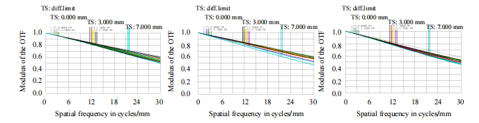
(a) MTF curves when EFL=20mm (b) MTF curves when EFL=60mm (c) MTF curves when EFL=120mm
Fig.3 MTF curves of LWIR continuous zoom optic system
2.2 Point diagram
Figure 4 shows the point diagrams of 6 different fields of view when the focal length of this design system is 20mm, 60mm and 120mm. It can be seen from the figure that the diffuse spots in each field of view of the system are close to the diffraction limit (the black circle in the figure is the airy disk range), and its root mean square radius does not exceed 6.3μm at the maximum, which is smaller than the pixel size of 17μm×17μm. This design achieves a higher resolution and can meet the matching requirements of the high-definition uncooled detector in this system.
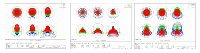
(a) Spot diagrams when EFL=20mm (b) Spot diagrams when EFL=60mm (c) Spot diagrams when EFL=120mm
Fig.4 Spot diagrams of LWIR continuous zoom optic system
2.3 The zoom curve of the zoom group and the compensation group
The design of the zoom optical system must ensure the stability of the image surface, and the design of the zoom curve has a decisive influence on the product’s image surface stability, image quality, and processing and assembly process complexity during the zooming process.
In practical applications, if the design of the zoom cam curve is not smooth enough, and there are jump curvatures or extreme points in some positions, it will increase the difficulty of processing the cam mechanism, causing the system to be unsmooth and smooth when zooming, and easy to jam.
This design uses an electromechanical system to drive the zoom group and compensation group to move non-linearly to achieve 6×continuous optical zoom, and optimize the design for its smoothness.
Figure 5 shows the continuous zoom curve of the system: the ordinate is the focal length of the zoom system, and the abscissa is the movement distance of the zoom group and compensation group relative to the origin of the system. Figure 5(a) is the zoom curve before the optimization design, there is a local curvature jump; Figure 5(b) is the zoom curve after the optimization design, the zoom curve after optimization is smooth and continuous, which is beneficial to the processing of the cam mechanism]. The system's optical axis jitter is less than 3 pixels in the 20~120mm zoom stroke.
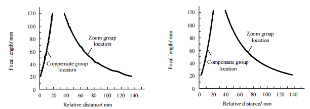
(a) Zoom loci curves before optimization (b) Zoom loci curves after optimization
Fig.5 Zoom loci curves of LWIR continuous zoom optic system
3. Experimental results
In this paper, a high-resolution long-wave infrared continuous zoom optical system is correspondingly designed based on the 640×512-element uncooled detector used. Figure 6 is the original image of the image corresponding to different focal lengths when using this optical system to shoot a building about 2~3 km away.
(a), (b), (c), (d), and (e) in the figure correspond to focal lengths of 20mm, 40mm, 60mm, 90mm, and 120mm, respectively. It can be seen from Fig. 6 that during the zooming process, the image obtained by the system has stable image quality, high resolution, clear details, high transmittance, and good application prospects.
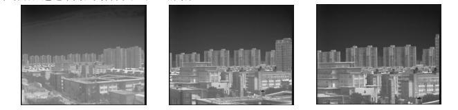
(a)Image when EFL=20mm (b) Image when EFL=40mm (c) Image when EFL=60mm
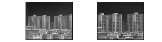
(d) Image when EFL=90mm (e) Image when EFL=120mm
4.Conclusion
Based on the design theory of continuous zoom optical system and the requirements of practical engineering applications, this paper designs a high-resolution long-wave infrared continuous zoom optical system suitable for 640×512 element uncooled detectors. The system uses 5 germanium single crystal lenses and 1 chalcogenide glass lens, with relatively low cost, small size, and lightweight, and is easy to install and carry.
The system also uses a mechanical compensation zoom method to achieve a smooth continuous zoom in the range of 20~120mm, and the working distance can reach 5m~5km. The field of view can reach 33.8°×25.7° (at 20mm focal length) to 4.6°×3.4° (at 120mm focal length), real-time tracking can be achieved when the field of view is changed, and it is suitable for tracking high-speed moving targets.
The image quality of the system is excellent, the MTF and spot diagram data are close to the diffraction limit, and the actual shooting effect is good. The curve of the zoom cam has been optimized by design, and the zoom is smooth; the image surface is stable, and the axis of the optical axis is less than 3 pixels for continuous zooming.
The design has been proved to meet the requirements of various indicators through actual tests. As a high-resolution infrared system that replaces refrigerated products, it is characterized by the combination of continuous zoom, high resolution, and lower cost, and realizes it.
On the basis of ensuring high system performance and product grades, we save as much as possible the cost of design, processing, testing, and assembly, and strive to find the best combination of performance and cost. This design is used in security, tracking, detection, and other fields that have high practical value.
Authors: Bao Jiaqi, Ji Zijuan, Ge Zhenjie, Li Nan, Yu Kan, Yin Juanjuan
Journal source: Opto-Electronic Engineering Feb 2014
References:
[1] LUO Shoujun,HE Wubin,LI Wenhu,et al. Design of middle infrared continuous zoom optical system with a large FPA [J]. Optics and Precision Engineering,2012,20(10):2117-2121.
[2] JIA Xingrui,LI Xunniu,WANG Haiyang,et al. Design of a LWIR Continuous Zooming Optic System with Large Zooming Range [J]. Infrared Technology,2012,34(8):463-466.
[3] ZHANG Liang, LIU Hongxia. Optical system design of long wave infrared zoom lens [J]. Infrared and Laser Engineering,2011,40(7):1279-1281.
[4] CHEN Lüji,LI Ping,SUN Qiyan. Design of LWIR Zoom Optical System with 20:1 Zoom Range [J]. Infrared Technology,2012,34(8):458-462.
[5] LIU Feng,XU Xiping,SUN Xiangyang,et al. Design of high zoom ration thermal infrared zoom optical system [J]. Journal of Applied Optics,2009,30(6):1020-1023.
[6] BAI Yu,YANG Jianfeng,MA Xiaolong,et al. Diffractive/Refractive Infrared Continuous Zoom System in 8~12μm [J]. Infrared Technology,2008,30(9):505-508.
[7] Mark C. Sanson and James Comell,MWIR Continuous zoom with large zoom range [C]// Infrared Technology and Applications XXXVI,Orlando,Florida,April 05,2010,7660:1-12
[8] LAN Ning. Optical design of optically compensated long wavelength infrared zoom system [J]. Optical Instruments,2011,33(3):53-56.
[9] YANG Le,SUN Qiang,WANG Jian,et al. Design of long-wave infrared continuous zoom optical system [J]. Infrared and Laser Engineering,2012,41(4):999-1003.
[10] LIU Jun,GAO Ming. Optical System Design [M]. Xi’an:Xi'an Electronic Science &Technology University Press,2006,174-175.
[11]LI Yonggang,ZHANG Bao,DING Jinwei. Mechanism Design of Continuous Infrared Zoom Lens [J]. Journal of Changchun University of Science and Technology:Natural Science Edition,2009,32(1):60-63.
[12] FISCHER R E,GALEB B T. Optical system design [M]. New York:Mc GRAW Hill,2000.