
Design of Infrared Dual-field Focusing System Based on DSP
The dual-field infrared optical system can provide two images with different magnifications and different fields of view at the same time. A large field in the system is low resolution and is used to search targets in a large range; a small field is used to identify, analyze and confirm specific targets. Therefore, the infrared dual field of view system is widely used in airborne, vehicle-mounted, and other optoelectronic reconnaissance equipment.
In this paper, according to the working characteristics and technical requirements of the dual-field infrared optical system, a set of the optical lens focusing systems based on DSP is designed. By applying the design idea of optomechanical integration, the functions of fast switching and focusing of large and small fields of view are realized through parallel moving of the optical lens group along the axis.
1 The design of the focusing system
1.1 Selection of focusing method
Usually, the dual field of view zoom system is divided into two categories: In the dual field of view infrared lens, optical lens group moving in and out switching zoom system and two-position zoom system. The switchable zoom system requires inserting part of the lens into the proper position to change the focal length of the optical system, so the lateral size is large. The dual-position system changes the focal length of the system by changing the axial distance of the lens group, which can effectively reduce the volume of the system, and can realize the functions of the field of view switching and precise focusing at the same time.
Considering the quality and space size requirements of the overall system, a dual-position zoom system that moves the optical lens group in parallel along the axis is adopted. The two-position zoom system consists of a front fixed group, a moving lens group, and a rear fixed group. Its working principle is shown in Figure 1. When the moving lens group is in position 1, the system is in a state of short focal length (large field of view), and when the moving lens group is in position 2, the system is in a state of long focal length (small field of view).
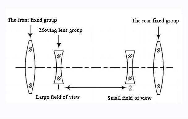
Figure 1 Schematic diagram of dual-field infrared optics
1.2 Design of focusing motion system
The entire focusing motion system is composed of a closed-loop control system with a DSP control module as the core. The schematic diagram of the system is shown in Figure 2. It is mainly composed of the following parts: DSP control module, servo motor, lead screw, sliding module, precision linear guide, linear grating ruler, etc. The DSP module controls the rotation of the motor after accepting the control command of the host computer and changes the rotational motion of the motor into the axial linear motion of the moving mirror group through the motion mechanism of the screw guide. The linear grating ruler detects the current position of the lens group sliding and feeds it back to the DSP. The DSP control module compares the current position of the moving lens group with the given position of the system, and further controls the motor to drive the lens group to move along the axial direction until the moving lens group reaches the given position of the system.
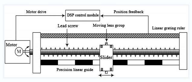
Figure 2 Schematic diagram of the focusing system
2 Focusing on system hardware design
The hardware circuit of the focusing system is based on the DSP controller.TMS320LF 2407A is a 16-bit fixed-point digital signal processor. It integrates high-speed digital signal processing capabilities and optimized peripheral circuits suitable for motor control, providing the motor control with a set of digital solutions with high precision and high performance at the same time. The design of the peripheral circuit of the control system revolves around TMS320LF 2407A, which is mainly composed of the following basic parts: the serial communication interface circuit with the host computer, the power drive circuit, and the position detection circuit, and so on. The block diagram of the control system is shown in Figure 3.
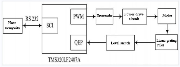
Figure 3 DSP control system hardware block diagram
2.1 SCI serial communication circuit
The system can realize the communication between DSP and the host computer through the serial communication module SCI integrated by the TM S320LF 2407A chip. The circuit adopts the MAX232 driver chip host computer that conforms to the RS232 standard to send control commands to the DSP control module. The DSP system responds to the control commands by calculating the given position of the moving lens group, controlling the motor movement to complete the system focusing, and meanwhile, sending feedback of the current working state of the focusing control system to the host computer.
2.2 Position detection circuit
The key to accurate position control of the moving lens group is the detection of its displacement. The RGH22 precision grating ruler of Renishaw Company in the United Kingdom is selected as the position sensor with a resolution of 2μm. The output signal is two frequency changes and orthogonal (that is, a pulse with a phase difference of 90°). Its reading head has reference zero and double limit switches. The reference zero provides a repeatable reference origin or zero point, and the limit switch can output a signal when the axial movement reaches the limit points at both ends to stop the motor.
Each event manager EV of TMS320LF 2407A contains a quadrature decoded pulse circuit QEP, which can encode and count the quadrature decoded input pulses generated by the grating ruler. After the grating ruler generates the quadrature encoding pulse and sends it to the quadrature encoding circuit, the QEP circuit can determine the moving direction of the moving lens group by detecting the sequence of the two sequences, and the current displacement and speed of the moving mirror group can be calculated by the pulse count and pulse frequency. Since the output of the grating, the ruler is a 5V digital level signal, and the DSP can only accept the 3.3V level signal, the SN74LV C245 chip is used as the level conversion interface circuit between the DSP and the grating reading head.
2.3 Motor drive circuit
In the focusing system, the PWM signal output by the DSP after processing the collected information is not enough to drive the motor directly, and a driver chip is needed to convert it into a drive signal that can drive the motor. The motor drive circuit adopts the motor drive chip L298N of SGS Company. It is a double H-bridge motor chip with constant voltage and constant current, which can control two DC motors at the same time, and the output current can reach 2A. In order to reduce the influence of the drive circuit on the control system, the PWM signal generated by the DSP is in optoelectronic isolation by the TLP521 optocoupler and then sent to the drive chip L298, which makes the system control signal stable and reliable. Additionally, in practice, to protect the motor, two groups of freewheeling diodes should be added to the drive circuit.
3 Experimental results
The working band of the dual-field infrared optical system is 3-5 μm. The width of the field of view is 24°×18°, and the narrow field of view is 4°×3°. The short focal length is 20mm, and the long focal length is 145mm. The switching distance between large and small fields of view is 125mm, and the required positioning accuracy of the moving lens group is less than 20μm. Through experimental tests, the focusing system can switch between large and small fields of view within 1s, and the focusing accuracy can reach 5μm, which meets the positioning accuracy required by the system. Figure 4 shows the images of the infrared optical system under large and small fields of view, respectively.
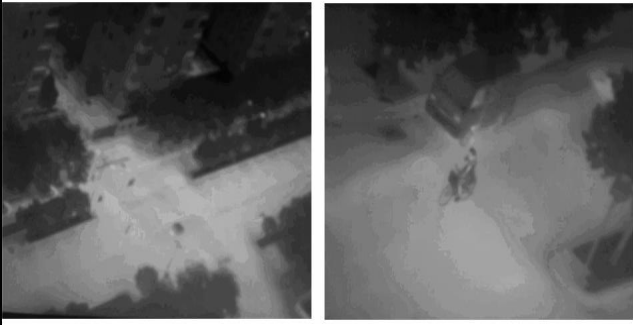
Figure 4 Optical system large and small field of view images
4 Conclusion
This paper introduces a dual-field infrared optical lens focusing control system, which adopts the axial movement of the movable lens group to realize zooming. Only one set of electromechanical devices is needed to realize the functions of the field of view switching and focusing at the same time, thus effectively controlling the axial dimensions, making its structure more compact. The control system adopts the high-performance TMS320LF 2407A chip as the control unit of the system, which makes the design of the entire hardware circuit simple and reliable. It meets the requirements of the infrared optical imaging system for the fast field of view switching and high focusing accuracy.
Quanhom is a professional custom infrared lenses and systems components supplier. Our state-of-the-art R&D team excels in seamlessly designing and manufacturing your thermal infrared optics product concepts. From simple infrared lens element subassemblies to sophisticated and reliable complex optomechanical and electro-optical assemblies. If you need, please contact us.
References
[1] Ren Deqing. The optical design of infrared dual-field lens[J]. Infrared Technology, 1998,20(3):19-22.
[2] Chen Lvji. Dual field of view infrared optical system for uncooled focal plane thermal imager[J]. Infrared Technology, 2007,29(11):645-647.
[3] Yang Yulong, Guan Fulin, Zhang Tuqiao, et al. Model design and control of focusing mechanism of imaging mirror of space solar telescope [J]. China Mechanical Engineering, 2006, 8(17): 313-316.
[4] Liu Heping, Yan Liping, Zhang Xuefeng, et al. TM S320LF240x DSP Structural Principle
and application [M]. Beijing: Beijing University of Aeronautics and Astronautics Press, 2002.
[5] Liu Jinkun. Advanced PID Control Matlab Simulation [M]. Beijing: Electronic Industry Press, 2004.
[6] Hu Jin, Zhong Xingrong, Wang Jiajun. Research on near-infrared imager based on frequency domain method
[J].Modern Electronic Technology, 2007, 30(22):125-126.
[7] Li Yunhong, Li Junhua, Li Pei. Application of infrared thermal imaging technology in power plants [J].
Modern Electronic Technology, 2008, 31(6):181-183.