

Design of LWIR Zoom Optical System with 20:1 Zoom Range
An infrared zoom optical system with a zoom range of 20:1 is designed based on a long-wave 384×288 QWIP detector. The operating wavelength range is from 8 to 9µm, the F-number is 3, and the focal length is continuously changeable from 18.5 to 367 mm.
The system consists of a mechanically compensated zoom object and a second imaging system, including 6 lenses and 2 reflectors,and has the advantages of the large zoom ratio, high resolution, small size, and excellent image quality. The zoom optical system image quality is evaluated with ZEMAX optical design software, and the results show that the MTF in the whole focal approach has a diffractive limit at the Nyquist frequency of 20 lp/mm.
An infrared continuous zoom system is a system in which the focal length can be continuously changed, and the image surface remains stable and the image quality is maintained during the zooming process. It can obtain different sizes of field angles, different sizes of images, and different scene ranges. The continuity of the image can be maintained during the conversion process, and it is widely used in many fields of the national economy and defense industry.
High resolution, high magnification continuous zoom thermal imaging system has a wide range of applications in the military field. High resolution means long focal length, which can realize the observation and recognition of ultra-long distance targets; high magnification means large zoom ratio, which can be realized large magnification for small suspected targets; continuous zoom means continuous detection, tracking, recognition, and aiming of targets can be achieved without losing targets when changing magnification, which is especially beneficial for searching and tracking high-speed moving targets.
Quantum well detectors have received extensive attention and rapid development due to their advantages such as good uniformity, low cost, high performance, multicolor, and large array production. At present, in advanced countries such as the United States and Europe, the quantum well focal plane has developed into one of the two main branches of long-wave refrigerated focal plane devices. Many countries have developed thermal imagers based on quantum well detectors of different sizes.
This article will discuss the mechanical compensation continuous zoom infrared optical system, and for the 384×288 long-wave quantum well focal plane detector, a 20x long-wave infrared continuous zoom optical system is designed with only 6 lenses, which has high transmittance and resolution. The advantages of high rate, large zoom ratio, compact structure, lightweight, and high image quality are in line with the current research direction of infrared continuous zoom system.
1. Calculation of the initial structure of the mechanically compensated continuous zoom optical system
The basic principle of the mechanical compensation zoom optical system is to use the two components of the zoom group and the compensation group to move at the same time to achieve continuous changes in the focal length while maintaining a stable image surface, and maintaining good image quality during zooming.
Usually, the initial parameters of the system are determined through Gaussian optical calculations according to the requirements that the system needs to meet.
Figure 1 shows the optical principle of the negative group compensation zoom system. In the figure, 1 is the front fixed group; 2 is the zoom group; 3 is the compensation group; 4 is the rear fixed group. In order to achieve zooming, zoom group 2 moves linearly along the optical axis, and its vertical axis magnification changes from β2 to β2*.
At this time, the image point also moves accordingly. To ensure that the image point remains unchanged, compensation group 3 needs to be the corresponding axis to move. Change the magnification of the compensation group from β3 to β3*. Then the zoom ratio of the system is:

The initial magnification of the zoom group:

The initial magnification of the compensation group:

The magnification of the zoom group:

Formula:

Magnification of compensation group:

Moving amount of zoom group:

The amount of movement of the compensation group:

The interval between the pre-fixed group and the zoom group:

The interval between the zoom group and the compensation group:

The interval between the compensation group and the post-fixed group:
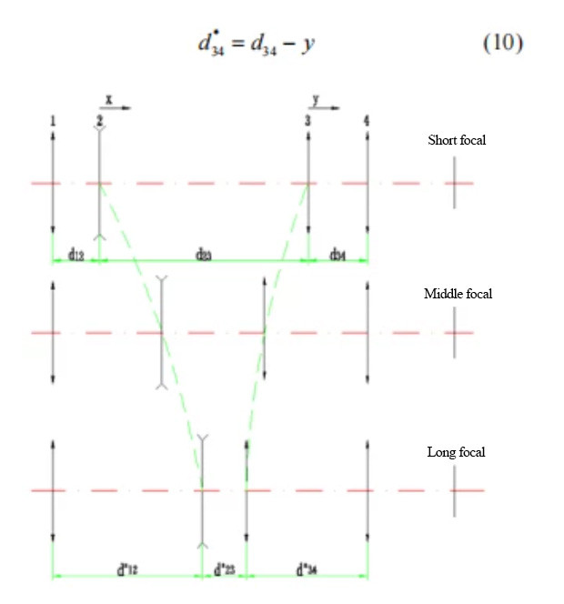
Fig.1 Principle of mechanically compensated zoom optical System
2 Design example
2.1 Design index
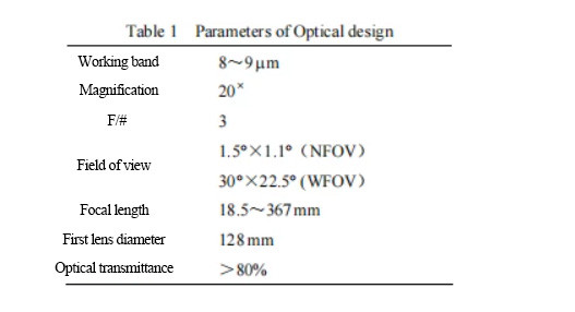
For the long-wave quantum well focal plane detector, the array size is 384 × 288, and the pixel size is 25 μm × 25 μm. Considering the requirements of volume, weight, performance, and cost, the design index of 20× continuous zoom infrared optical system is as follows in Table 1.
2.2 Design results
For the long-wave quantum well staring focal plane detector, according to the technical requirements of the zoom system, the initial parameters of the system are determined according to the methods and steps introduced in section 2, and then the ZEMAX optical aided design software developed by the US Focus company is used to optimize the design and design. Need to consider the cold diaphragm matching, cold reflection phenomenon, processing accuracy, system volume, and weight, and other issues.
The zoom system adopts a mechanical compensation form, which is composed of a front fixed group, a variable magnification group, a compensation group, and a rear fixed group. Each lens group is composed of a germanium lens, and its contribution to the optical power of the system is positive, negative, and positive. In order to correct aberrations, improve image quality, reduce the number of lenses as much as possible, and increase transmittance, a binary diffractive surface and two high-order aspheric surfaces are introduced.
In order to help compress the aperture of the first objective lens and keep the detector with 100% cold screen efficiency, a secondary imaging design is adopted. The relay group is composed of Ge and ZnSe.
The germanium material has the characteristics of low dispersion and high refractive index and has good dispersion performance at 8-12 μm. However, it is difficult to correct chromatic aberration for complex zoom systems with only one material. ZnSe Mainly plays the role of achromatic aberration.
The total length of the optical system is less than 390 mm. In order to facilitate the realization of compact structure and micro-scanning technology [8], two reflectors placed at 45° are used to fold the optical path twice. The overall size is less than 230 mm×175 mm×128mm (length× Width × height), the design result is shown in Figure 2.
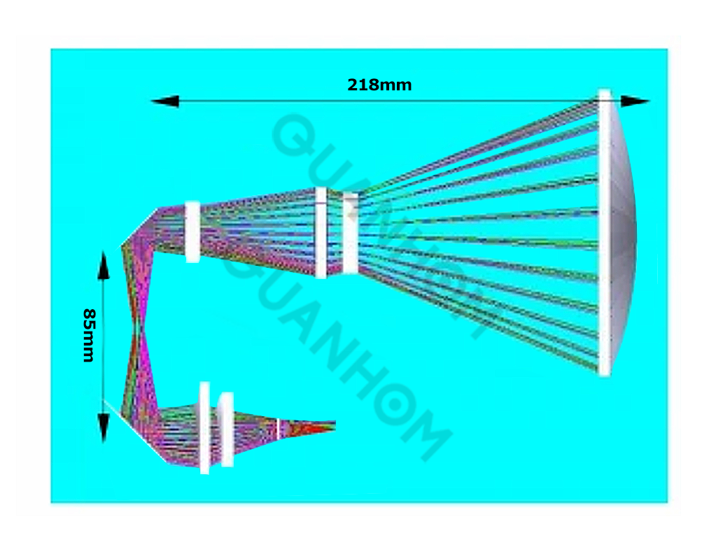
Fig.2 Schematic of zoom optics
The continuous zoom range of the system is 18.5~367 mm, corresponding to a field of view of 1.5°×1.1°~30°×22.5°, and any field of view can guarantee the image quality during the zooming process. The zoom function is completed by the variable magnification group and the compensation group.
The variable magnification group is used for variable magnification with a stroke of 74 mm; the compensation group is used for compensation of image plane displacement, focusing, and temperature compensation, with a stroke of 48 mm. The running track of the zoom group and compensation group is smooth, and the zoom process and compensation curve are shown in Figures 3 and Figure 4.
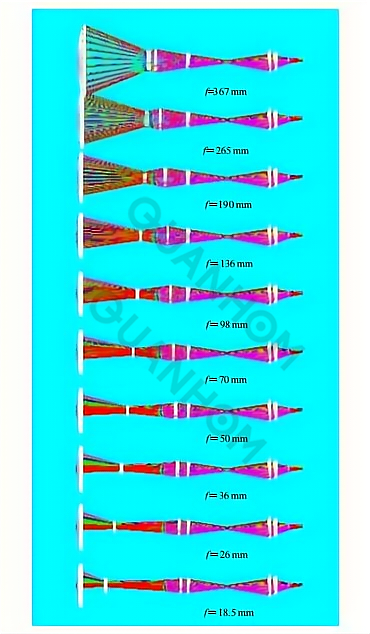
Fig.3 Conceptual of zoom optical System
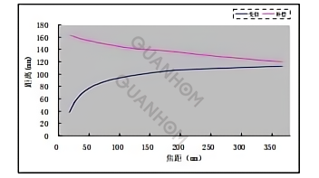
Fig.4 The curves of zoom and compensation
3 Image quality evaluation
3.1 Transfer function
The modulation transfer function (MTF) is the most comprehensive criterion among all-optical system performance criteria. Especially for imaging systems, it is currently recognized as an evaluation index that can fully reflect the actual imaging quality of the system in modern optical design. After the optimized design, the image surface of the system is stable and the image quality is excellent during the zooming process.
Figure 5 shows the optical modulation transfer function diagrams for different focal lengths. It can be seen from the diagram that the MTF at the Nyquist frequency (20 lp/mm) is close to the diffraction limit (the upper black solid line is the diffraction limit). ), indicating that the imaging quality of the zoom system is excellent, which is sufficient to meet the imaging quality of the optical system in the entire focal length change range.
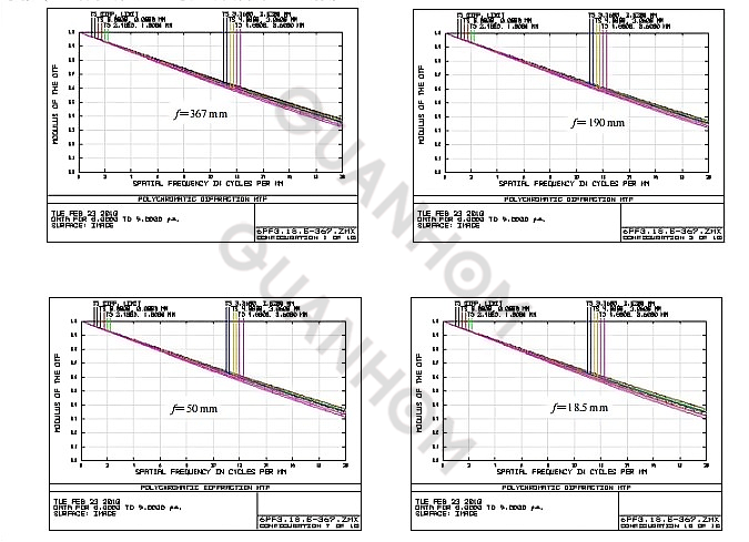
Fig.5 MTF curves of zoom optical system
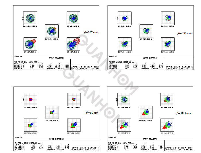
Fig.6 Spot diagrams of zoom optical system
3.2 Point diagram
The spot diagram is the geometric image spot formed by the optical system when imaging a point target. It is an important indicator for evaluating the imaging quality of the optical system. The root means square diameter value reflects the concentration of light energy, which is more reflective than the geometric maximum diameter value. The imaging quality of the system. In the optical design, the root means the square diameter of the point target is expected to be less than one-pixel size.
Figure 6 shows the plots of different focal lengths. It can be seen that the maximum root means square radius (RMS) of the system is 5.7 mm, which is within one pixel of the detector (the black box in the figure, 25 μm×25 μm), Which shows that the zoom optical system and the infrared detector have good matching, which satisfies the requirements of the system.
4. Conclusion
In this paper, aiming at the 384×288 long-wave quantum well staring focal plane detector, the mechanical compensation method is used to achieve continuous zooming in the range of 18.5~367 mm with only 6 lenses. The relative aperture remains unchanged during the zooming process, and the F-number is constant at 3.
The ZEMAX optical design software was used to evaluate the image quality. The results show that at the center frequency (20 lp/mm), the MTF of each field of view at each zoom position is close to the diffraction limit, and the image quality is good. And the use of mirrors to fold the light path, to achieve a compact structure.
This is in line with the development trend of infrared continuous zoom systems with high image quality, large zoom ratio, high resolution, small size, and lightweight. It satisfies the needs of practical applications and can be widely used in airborne stable aiming or early warning systems, ground Air defense alert systems, shipborne reconnaissance and tracking systems, battlefield reconnaissance search and surveillance systems, weapon platform aiming and tracking system, etc.
The long-wave infrared continuous zoom lens designed and manufactured by Quanhom takes into account the lightness of the aperture and the cost, which is very suitable for remote monitoring and homeland security and supports the SXGA (1280x1024 12μm) format. If you have a demand for this, you can send your demand to us, and we will give you a satisfactory answer as soon as possible.
As a professional manufacturer of thermal infrared lenses (including LWIR, MWIR, and SWIR), we have won praise and trust from many customers with our excellent technology and high-quality products. We have a professional production team and a range of quality control. At the same time, we can also provide thoughtful one-stop service according to customer needs. If you are interested in our LWIR lens, please contact us immediately!
Authors: Chen Luji, Li Ping, Sun Qiyan
Journal Source: Infrared Technology Vol.34 No.8 Aug. 2012
Received Date: 2012-03-04
References:
[1] 许照东, 刘欣, 董涛. 机载高分辨率连续变焦红外热像仪设计[J]. 红外与激光工程, 2007, 36(5): 619-621.
[2] 陈吕吉, 李萍,马琳. 紧凑中波红外连续变焦光学系统设计[J]. 红外技术. 2010, 32(11): 645-648.
[3] 史衍丽. 国外量子阱红外焦平面探测器的发展概况[J]. 红外技术,2005, 27(4): 274-278.
[4] 李献杰, 齐丽芳. 量子阱红外焦平面阵列的商业化进程[J]. 红外与激光工程, 2007, 36(z): 175-182.
[5] Stefan Johansson, Optical for long-range camera modules with QWIP 640×480 detectors[C]//SPIE, 2003, 5074: 867 -873.
[6]Olivier Cocle, Francois-Hugues Gauthier, et al. QWIP thermal imager[C]//SPIE, 2003, 5074: 715-725.
[7] 王之江. 实用光学技术手册[M]. 北京: 工业出版社, 2007.
[8] 李林, 王涌天, 张丽琴, 等. 变焦距物镜高斯光学参数的求解[J]. 北京理工大学学报. 2003, 23(4): 424-427.
[9] Hyun Sook Kim, Wee Kyung YU, et al. Compact MWIR camera with 20x zoom optical[C]//SPIE, 2001, 4369: 673 -679.