

Design of Long Focal Infrared Folded Optical System for Multi-guided System
In recent years, with the rapid development of infrared detector technology, the pixel size of the detector has gradually decreased, and the size of the area array has gradually increased. At present, in the design of a mid-wave infrared long focal length optical system, due to the high price of large-diameter infrared materials, reflective structures are often used, but the field of view cannot be enlarged.
The folded infrared imaging system can combine the advantages of transmission and reflection, and has a larger telephoto ratio and field of view. Especially in the multi-mode hybrid guidance system, the optical system is required to have a low obscuration ratio and a compact structure to reduce the influence on the detection of other modes, and the advantages of this structure are more obvious.
Generally, the working environment temperature of a multi-mode guidance system is -50~70℃, and the refractive index of infrared material is greatly affected by temperature, which seriously reduces the imaging quality.
Current thermalization analysis for infrared systems. The diffractive element is mainly used to realize achromatic and athermal aberration by using its special dispersion properties. However, the diffraction efficiency of the diffractive element is also a problem to be considered, and it will introduce additional stray light to the system. In addition, electromechanical active focus compensation systems are also commonly used in the athermal design of infrared optical systems.
In view of the above analysis, a telephoto infrared folded system suitable for multi-mode guidance is designed in this paper. The wavelength range is 3.7μm-4.8μm, the F-number is 2, the cold diaphragm efficiency is 100%, and the heat dissipation difference is realized at -50~70℃, the image quality is close to the diffraction limit.
1. Catadioptric system
In order to meet the efficiency of the cold diaphragm, the mid-wave infrared system needs to match the exit pupil of the system with the cold diaphragm of the detector. If the RC mirror structure is used, the aperture of the secondary mirror will be too large, which will increase the blocking ratio of the system. The wave infrared reflection system is usually realized by means of secondary imaging, as shown in Figure 1. The front group adopts an R-C double reflection structure, and the rear group adopts a relay imaging system with a certain magnification.
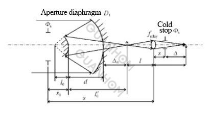
Fig.1Relayimagingsystem
The initial structure of the R-C system can be obtained from the curvature radius R1 of the primary mirror of the system, the blocking ratio α and the magnification β of the secondary mirror by the Gaussian formula:

The R-C system does not produce chromatic aberration and only needs to consider monochromatic aberration. In the case of aspheric aberration and coma, that is, SI=SII=0, it can be solved:
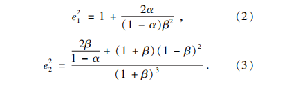
Therefore, after determining the focal length of the primary mirror and the blocking ratio and magnification of the secondary mirror, the initial structure of the R-C system can be determined.
The relay imaging system has a certain magnification W, and the magnification can be obtained by using the focal length f1 of the front group reflection system and the total focal length f of the system:

The specific initial structural parameters of the two-mirror system for relay imaging are as shown in formula (5):

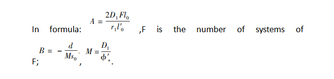
The physical meaning of each variable in formula (5) is shown in Figure 1. Therefore, by formula (5), as long as the structure of the two-mirror system and the parameters of the detector are determined, the conjugate imaging position and focal length of the relay system can be calculated. In order to meet the large field of view and achromatic requirements, the relay system usually needs 2 to 3 lenses.
In summary, the initial structure of the entire optical system can be determined by using formulas (1)~(5).
2. Athermalization analysis
Because the refractive index temperature coefficient dn/dt of infrared optical materials is much larger than that of common glass materials in the visible region, for example, the dn/dt value of germanium (Ge) single crystal is about 396×10-6℃, while the dn/dt value of K9 glass is about 396×10-6℃. The value is only 2.8×10⁻⁶°C.
The change of the refractive index of infrared materials at different temperatures will cause the change of the optical path of the light in the optical system. In addition, the change of temperature will also change the thickness and radius of curvature of the lens, which will reduce the quality of imaging. It can be seen that when the infrared optical design is carried out, the athermal analysis must be carried out.
In order to achieve thermalization of the optical system, the methods currently used can be divided into three categories: mechanical passive, electromechanical active compensation, and optical passive. In this paper, the athermalization of the optical system is realized by the optical passive method.
The front group of the optical system is a total reflection structure. When the mirror is affected by uniform heat and reaches a thermally stable state, the change of its surface shape is small, and the aberration introduced by a single mirror can be ignored. However, the expansion or contraction of the connecting structure of the primary and secondary mirrors will change the spacing, which is the main source of thermal aberrations in the front group.
The sources of aberration generated by the temperature difference of the relay imaging system include lenses and structural parts. The lens structure should be made of materials with a small linear expansion coefficient, among which titanium alloy not only has a small linear expansion coefficient, but also is light in weight and high in hardness, and is an ideal material for structural parts.
This can reduce the difficulty of heat dissipation difference of the system and improve the structural strength, but it will increase the cost. The rear group adopts a fully transmissive structure, which needs to be achromatic separately.
At the same time, it also needs to cooperate with the front group to realize the athermalization of the whole system and bear a certain optical power. This makes the design of the latter group more difficult, so a three-piece structure is proposed to meet the following equations:
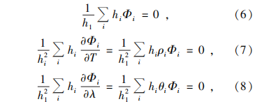
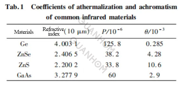
In the formula, hi is the height of the first paraxial ray in each lens group, and when the system adopts a close-contact lens structure, hi = h1; Φi is the optical power of the i lens; Φ is the total optical power of the rear group; pi and Φi are the athermal and achromatic coefficients of the material.
By analyzing the temperature characteristics of the current commonly used mid-wave infrared materials in China (as shown in Table 1), the data in Table 1 are put into formulas (6)~(8), and after calculation, the 3 Ge, ZnSe, and ZnS are used. This kind of material can realize the design of the post-group relay imaging system and meet the requirements of heat dissipation.
In order to correct the high-order spherical aberration and coma in the system, reduce the system complexity and improve the imaging quality, high-order aspheric surfaces are used on the front surfaces of Ge and ZnSe.
3. Optical system parameters
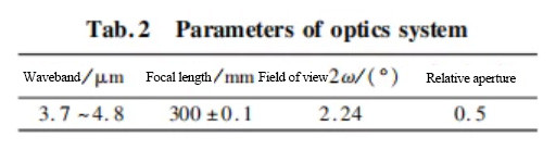
The optical system is used in the mid-wave infrared and millimeter-wave composite guidance system, so according to the general requirements, the main mirror is shared by millimeter-wave and medium-wave, its surface shape is paraboloid, and the focal length F1=240 mm. The mid-wave infrared imaging system adopts a cooled detector with F/2, 320×256 pixels, and a pixel size of 30μm. The optical system parameters are shown in Table 2.
The design indicators are as follows. The optical system structure should be compact, the telephoto ratio should be less than 0.6, and the central occlusion should be less than 30%. In order to suppress the influence of background radiation to the greatest extent, it is required to achieve 100% cold aperture matching. The design requires that the energy concentration in the pixel of the full field of view is more than 85%, and the optical passive thermalization can be realized in the temperature range of -40 ~ 60℃.
4. Design results
In the design, the surface shape of the main mirror is a paraboloid, and the focal length F1 = 120mm, which not only meets the requirements of millimeter-wave imaging, but also facilitates the installation and detection of the main mirror, and the secondary mirror is a hyperboloid.
Considering the aperture of the secondary mirror, the obscuration ratio, and the distance between the two mirrors, the focal length of the front group is set to 300 mm, the magnification of the relay imaging system is -1, and the three-piece structure is adopted, which are Ge, ZnSe and ZnS respectively.
Due to the long focal length and large aperture of the system, it is difficult to aberration-corrected. In the design, two high-order aspheric surfaces are set up on the front of Ge and ZnSe respectively to correct the spherical aberration, coma, and astigmatic monochromatic aberration in the system. The physical properties of these two materials are suitable for processing high-order aspheric surfaces.
Using the user-defined constraint function of the ZEMAX-EE software of Focus Software, the system is optimized globally and locally, and finally, the optical system design shown in Figure 2 is realized. The diameters of the transmission elements are all less than 25 mm, which is beneficial to the control of system quality and cost.
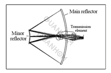
Fig. 2 Configuration of the optical system
Figures 3 to 5 are the optical transfer function curves of the optical system at 20, -50, and 70 ℃, respectively. It can be seen from the figure that the characteristic frequency of the detector is 17 lp/mm, whether it is the central field of view or the edge The transfer function of the optical system is close to the field of view.
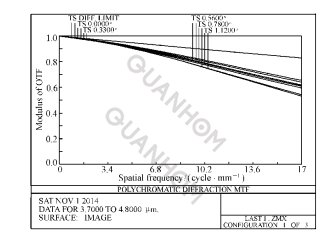
Fig. 3 Modulation transfer function at the temperature of 20℃
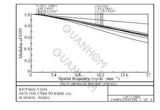
Fig. 4 Modulation transfer function at the temperature of - 50℃
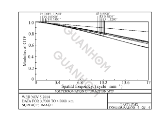
Fig. 5 Modulation transfer function at the temperature of 70℃
Figure 6 shows the energy concentration curve of the optical system at 20 °C. It can be seen from the figure that within a pixel size of 30μm, the energy concentration is more than 90%, which meets the requirements of the infrared imaging system.
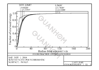
Fig. 6 Energy encircle curve at the temperature of 20℃
5. Tolerance analysis
In order to verify the feasibility of the processing of the optical system and reduce the processing cost, it is necessary to carry out a reasonable allocation of tolerances. By repeatedly using Zemax's Monte Carlo analysis, we obtained the tolerance distribution shown in Table 3, in which the processing and assembly precision of the primary and secondary mirrors is relatively high, but also within the scope of existing processing and assembly techniques.
At 20 °C, the corresponding Monte Carlo simulation transfer function is shown in Figure 7. The results show that under the influence of various random errors, the probability that the optical transfer function of the system is higher than 0.55 is greater than 90%, and the system meets the actual processing and adjustment. imaging requirements.
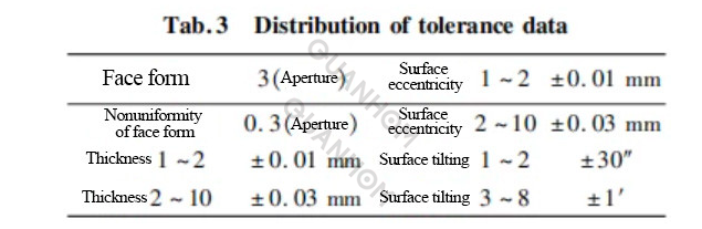

Fig. 7 MTF curve after Ment-Karol simulation at the temperature of 20℃
6. Stray light analysis
In the infrared optical system, the influence of stray radiation on the imaging quality becomes a factor that must be considered. The stray light suppression of the folded secondary imaging system can adopt the following methods: First, for the stray light from outside the imaging field of view, the primary mirror shading tube and the secondary mirror shading tube can be used, and the inner and outer surfaces can be further processed with extinction threads to effectively reduce the primary and secondary mirrors.
The stray light entering the detector is reflected multiple times, and the stray light incident outside the field of view of the main mirror can be controlled by setting the length of the main mirror barrel; secondly, the secondary imaging part is used, and the field diaphragm limit is added near the primary imaging surface Entrance beam.
Finally, Lighttools is used in this paper to separate the effective light from the stray light by using the inverse light path method and finally obtain the stray light coefficient expressed as a percentage.
During the analysis, because the transmittance of each surface was not actually measured, the reflectivity of 2% was taken according to experience, and 10 rays were traced. The light energy of the receiver on the right accounted for 96% of the total output energy.
It can be analyzed that the energy of the stray light of the optical system accounts for 2% of the energy received by the detector, which can meet the needs of imaging detection.
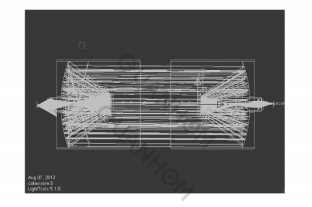
Fig. 8 Ray trace based on Lighttools
7. Conclusion
In this paper, a compact medium-wave folded optical system is designed for use in multi-mode hybrid guidance. The system has a low obscuration ratio, small size, and excellent imaging quality, with a heat dissipation difference of -50 ~ 70 ℃. Tolerance analysis results show that the system meets the requirements of processing and assembling imaging.
Finally, some measures to eliminate stray light are proposed, so that the system can effectively suppress the solar background radiation and the stray radiation inside the system, thereby improving the signal-to-noise ratio.
As an experienced manufacturer of Opto-electromechanical components, Quanhom is committed to providing users with a variety of thermal infrared cameras (LWIR, MWIR, and SWIR) of excellent quality. We have a good reputation in the industry by virtue of leading R&D technology and excellent manufacturing technology. And our products are sold all over the world and have received praise and trust from many customers. If you want to learn more about our related services, you can send us your needs, and we will give you a satisfactory answer as soon as possible.
Authors: Yu Linyao, Wei Qun, Zhang Tianyi, Wang Chao, Han Jingzhuang, Zhu Ruifei, Song Baoqi, Jia Hongguang
Journal source: Chinese Optics Vol. 8 No. 2 Apr. 2015
Received date: 2014-10-17; Revised date: 2015-01-15
References:
[1] XUE H. Optical design of infrared search and trace system[ J]. Acta Optica Sinica,2010,30(8):2383-2386. ( in Chinese)
[2] LUO SH J. Design of middle infrared continuous zoom optical system with a large FPA[J]. Opt. Precision Eng. ,2012,20 (10),2117-2123. (in Chinese)
[3] The methodic design of the IR imaging system with large aperture[J]. Acta Optica Sinica,2003,23(12):1475-1478. (in Chinese)
[4] Design of cryogenic infrared target simulation system with bidirectional and wide field for eliminating distortion[J]. Opt. Precision Eng. ,2012,20(12):2619-2625. (in Chinese)
[5] YU L Y,WEI Q. Design of compact integer structure of two-mirror system[ J]. Opt. Precision Eng. ,2013,21(3):561-566. (in Chinese)
[6] XIANG J SH,PAN G Q,ZHANG Y Q. The design of reflect and refractive reimaging infrared optic system used in air to air missile[J]. Infrared Technology,2011,33(8):457-459. (in Chinese)
[7] XIONG Y J,WU H P,LV ZH SH. Performance and structural form analysis of military infrared optical system[J]. Infrared Technology,2010,32(12):688-695. (in Chinese)
[8] DONG K Y,WANG J,SUN Q. Design of an airborne dual field of view middle wave infrared optical system[J]. Chinese Optics,2012,5(6):596-601. (in Chinese)
[9] LIU Y,AN X Q,DENG J. Removal of stray radiation from warm shields in cooled infrared optical systems[J]. Opt. Precision Eng. ,2012,33(1):186-190. (in Chinese)
[10] ZHAO N,XUE Y,WANG J. Analysis of stray radiation from infrared optical system with Monte-Carlo method[ J]. Chinese J. Optics and Applied Optics,2010,3(6):665-670. (in Chinese)
[11] NIU J X,ZHOU R K,LIU ZH H,et al. Analysis of stray light caused by thermal radiation of infrared detection system [J]. Acta Optica Sinica,2010,30(8):2267-2271. (in Chinese)