

Design of Long-wavelength Infrared Athermalization Lens for Large-array Detector
With the development of infrared optics, there is a high demand for infrared lenses in both military and civilian fields. Due to the low cost and simple structure of uncooled infrared lenses, the market demand is also increasing. In turn, the requirements for the field of view and environmental adaptability of uncooled lenses are getting higher and higher, especially in high and low-temperature environments.
At present, most infrared lenses on the market are matched with 384×288, 25μm or 640×512, 17μm detectors, while most athermal designs achieve high and low-temperature compensation through active mechanical compensation, and there are also a small number of products. The mechanical passive athermal design has been realized, and a small number of lenses have realized the optical passive athermal design.
Among them, this part of the optical passive athermalized lens is divided into two categories: one is realized by a combination of various materials and aspheric surfaces, most of these lenses are short-focus lenses; Derivative hybrid is realized, the image quality is good, and a major breakthrough has been made in athermalization.
In order to meet the needs of large area array detectors, athermalized design of high imaging quality and long-wave infrared lenses of medium and long focal lengths, a long-wave infrared optical athermalized lens is implemented in this paper. The lens consists of 4 lenses, using two infrared materials (HWS6 and zinc sulfide material) and aspherical surfaces to achieve optical athermalization design.
Since the detector used is a large area array, the number of pixels is increased, the resolution of the system is improved and the observed field of view, but at the same time, it will increase the difficulty of aberration correction of the optical system. This lens can match the 1024×768, 17μm large area array uncooled detector.
Through the optimization of the optical design software, the MTF value of the 0 fields of view is greater than 0.45, the MTF value of the one field of view is greater than 0.35, and the MTF value of the one field of view is greater than 0.35 in the operating temperature range of -60°C~+100°C, and at the spatial frequency of 30lp/mm, and at -60 In the temperature range of -60°C~+100°C, the MTF value of each field of view does not change much, and the optical athermalization design of a wide temperature range is realized.
The lens has the advantages of simple structure, large-area array, high resolution, wide operating temperature range, good manufacturability, etc., and can be used in fields such as seekers or space detection.
1. Optical system design
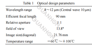
The large-area-array long-wave infrared optical athermalization lens is adapted to a 1024×768 uncooled long-wave infrared focal plane array detector, and the pixel size of the detector is 17μm. The design indicators of the infrared lens are shown in Table 1.
1.1 Design thinking
The focal length of the lens designed in this paper is 90 mm. In order to realize the optical athermalization design, the combination of infrared chalcogenide material and zinc sulfide is used to eliminate the influence of temperature on the optical system. Compared with germanium materials, the refractive index of chalcogenide materials varies less with temperature.
The temperature coefficient of the refractive index of germanium is 39.6×10⁻⁵/°C. When the ambient temperature changes greatly, athermal design is difficult, and the temperature coefficient of the refractive index of chalcogenide materials is only about 1/6 of germanium.
In order to make the optical system have good performance in a certain temperature range, the design must meet the requirements of optical power, chromatic aberration correction, and athermal aberration at the same time, that is, it must satisfy the power distribution formula, achromatic equation, and athermal aberration.
According to some reports at home and abroad: to satisfy the power distribution formula, the achromatic equation, and the athermal equation at the same time, it is necessary to change the curvature of the curved surface or use different materials to correct the aberration, which greatly increases the difficulty of the system design, and at least three kinds of materials are needed to make the system meet the requirements of optical power, chromatic aberration correction and heat dissipation at the same time, so the system structure is complicated.
But in this article, two kinds of infrared materials are used to cooperate with each other, that is, the chalcogenide material HWS6 (thermal expansion coefficient is 22×10-6/°C) and the zinc sulfide material, which bears a larger optical power. Athermalization design is realized by the combination of positive 1026 HWS6 lens, negative zinc sulfide lens, positive zinc sulfide lens, and negative HWS6 lens.
At the same time, because the air gap between the first and second lenses has a great influence on athermalization, the material of the lens barrel in this part is selected from invar material with a small thermal expansion coefficient (thermal expansion coefficient is 8×10⁻⁶/°C), and the rest are made of aluminum alloy material (thermal expansion coefficient is 23×10-6/°C).
Finally, the design of heat dissipation difference is realized through the above design ideas, and the structure is simple and the manufacturability is good.
In order to match the large area array detector, better correct the aberration of the optical system, and obtain an optical system with a large field of view, good imaging quality, and high resolution, two even-order aspheric surfaces are introduced in this paper. The system consists of 4 lenses, and the 2nd and 4th surfaces are even-order aspherical surfaces.
The first lens material is chalcogenide material HWS6. Although the material is relatively soft, it is difficult to prepare aspheric surfaces. However, with the progress of diamond turning technology, the process of turning aspheric surfaces on chalcogenide materials can be realized. Moreover, the material of the first lens is a chalcogenide material, and its aperture is relatively large, so using an aspherical surface on it can further improve the imaging quality. At present, chalcogenide lens elements with aspheric surfaces have been widely used in various infrared athermal lens designs.
The two even-order aspheric surfaces introduced are expressed as follows:
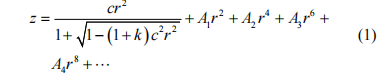
In the formula: c=1/r0; k=-e2; A1, A2, A3, A4, etc. are high-order coefficients, in most cases, A1 takes 0; r is the normalized radius coordinate; c is the reference surface of the aspheric surface or the curvature of the auxiliary sphere; k is the degree of taper. In the design of this paper, only the items r4, r6, and r8 in formula (1) are selected (wherein the second surface aspheric coefficient: A2=6.915×10⁻⁸, A3=8.094×10⁻¹⁴, A4=1.475×10⁻¹⁶; the aspheric coefficient of the fourth surface is: A2=2.569×10⁻⁸, A3=-7.371×10⁻¹¹, A4=3.531×10⁻¹³).
1.2 Design results
The optical structure diagram of the large-area array long-wave infrared athermal lens optimized by ZEMAX design software is shown in Figure 1. The structural parameters of the optical system are: the working band is 8-12μm, the center wavelength is 10μm, the effective focal length is 90 mm, the F-number is 1, the full field of view is 13.8°, the total length of the system is 108 mm, and the working temperature range is -60 °C ~100°C.
The system consists of 4 lenses, and the 2nd and 4th surfaces are even-order aspherical surfaces. The optical system is composed of "+", "-", "+", and "-" structures, and is designed to be athermalized by the cooperation of two infrared materials (chalcogenide material HWS6 and zinc sulfide material).
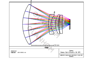
Fig.1 Schematic of optical system structure
2. Image quality evaluation
Figure 2 is the MTF curve of the system. Since the pixel size is 17 μm×17 μm, its limit resolution is FN=29.4 lp/mm. It can be seen from Fig. 2 that at a spatial frequency of 30 lp/mm, the MTF value of the 0 fields of view is greater than 0.45, the MTF value of the 1 field of view is greater than 0.35, and the MTF value of each field of view does not change in the temperature range of -60°C to +100°C. It realizes the optical athermalization design with a wide temperature range and meets the requirements of high image quality athermalization. Table 2 shows the MTF values of the optical system at various temperatures.
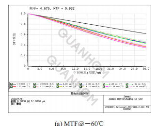
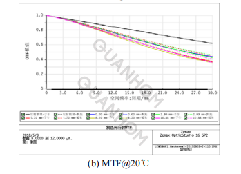
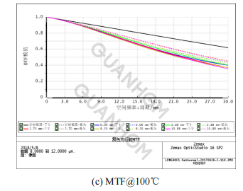
Fig.2 MTF curves of the system
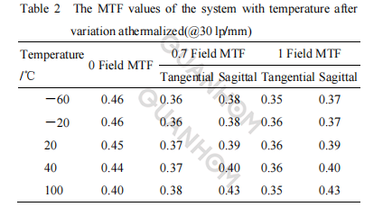
Table 3 shows the changes in focal length and speckle after athermalization. It can be seen from Table 3 that in the temperature range of -60 °C to 100 °C, the maximum dispersion spot radius is basically unchanged, which meets the requirements of the heat dissipation difference design. It shows that the system has better imaging quality and a better design of heat dissipation.
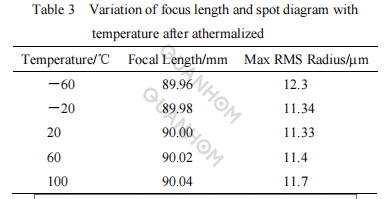
Table 3 shows the changes in focal length and speckle after athermalization. It can be seen from Table 3 that in the temperature range of -60 °C to 100 °C, the maximum dispersion spot radius is basically unchanged, which meets the requirements of heat dissipation difference design. It shows that the system has better imaging quality and a better design of heat dissipation.
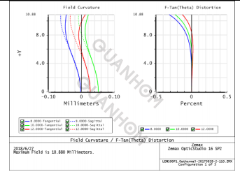
Fig.3 Field curves and distortion(@20°C)
3. Conclusion
In this paper, a long-wave infrared optical athermal lens with a focal length of 90 mm, a relative aperture of 1:1, and a full field of view of 13.8°is designed. Compatible with 1024°C×768, 17μm large area array uncooled detectors. For tracking, searching, monitoring, and other fields.
The lens has the advantages of simple structure, large-area array (large field of view), high resolution, wide operating temperature range, and good manufacturability. It has a wide range of application prospects in military and civilian fields, such as seekers or space exploration.
As a professional manufacturer of thermal infrared lenses (including LWIR, MWIR, and SWIR), we have won praise and trust from many customers with our excellent technology and high-quality products. We have a professional production team and a range of quality control. At the same time, we can also provide thoughtful one-stop service according to customer needs. If you are interested in our LWIR lens, please contact us immediately!
References:
[1] ZHANG Xinting, AN Zhiyong. Design of Infrared Athermal Optical System for Dual-Band with Double-Layer Harmonic Diffraction Element[J]. Infrared Technology, Acta Optica Sinica, 2013, 33(6): 0622004.
[2] BAI Yu, LIAO Zhiyuan, LI Hua, et al. Application of the chalcogenide glass in modern infrared thermal imaging systems[J]. Chinese Optics, 2014, 7(3): 449-455.
[3] ZHANG Xin, QIAO Yanfeng, ZHU Mingchao, et al. Two-Lens Athermalized Infrared Telephoto Objective[J]. Acta Optica Sinica, 2014, 34(8): 0822004.
[4] MI Shilong, MU Da, MU Meng. Athermalization of a compact LWIR optical system[J]. Infrared and Laser Engineering, 2015, 44(10): 3032-3036.
[5] JIANG Lun, HU Yuan, DONG Keyan, et al. Passive athermal design of dual-band infrared optical system[J]. Infrared and Laser Engineering, 2015, 44(11): 3353-3357.
[6] PAN Junhua. Design, Manufacture, and Testing of Asphere Optics[M]. Suzhou: publishing house of Suzhou University, 2004: 1-6.
[7] WEI Heli, CHEN Xiuhong, RAO Ruizhong, et al. A moderate-spectralresolution transmittance model based on fitting the line-by-line calculation[J]. Opt. Express, 2007, 15(13): 8360-8370.
[8] Safren H G. Computer code to calculate line by line atmospheric transmission spectra on a microcompute[R]. NASA-TM-100686, 1987.
[9] CHEN Fangfang, GENG Rui, LV Yong. Research on the transmittance
model of laser Infrared atmospheric transmission[J]. Infrared Technology, 2015, 37(6): 496-501.
[10] FANG Jing, LIU Wenqing, ZHANG Tianshu. A Line-by-Line trace gas
absorption model and its application in NDIR gas detection technology[J]. Spectroscopy and Spectral Analysis, 2008, 28(6): 1269-1271.
[13] Gamache R R, Kennedy S, Hawkins R, et al. Total internal partition sums for molecules in the terrestrial atmosphere[J]. J. Molecular Structure, 2000, 517-518(16): 407-425.
[11] Hui A K, Armstrong B H, Wray A A. Rapid computation of the Voigt
and complex error functions[J]. J. Quantit. Spectrosc. and Radiative Transfer, 1978, 19(5): 509-516.
[12] LIN Jieli. Research on spectral line profile and line width of high-resolution (saturation) molecular spectra and its application[D]. Wuhan: Institute of Physics and Mathematics the Chinese Academy of Science, 2000.
[13] Olivero J J, Longbothum R L. Empirical Fits to the Voigt Line Width: A
Brief Review[J]. Quantit. Spectrosc. and Radiative Transfer, 1977, 17(2): 233-236.