

A Review of Athermalized Infrared Imaging Technology Based on Wavefront Coding
Wavefront encoding infrared imaging technology is a computational optical imaging technology that combines two-step imaging of optical encoding and digital decoding. The wavefront coding athermalization infrared imaging system encodes and modulates the scene infrared radiation by adding a special surface optical phase plate near the aperture of the infrared optical system so that the output of the infrared focal plane detector in a wide ambient temperature range can be obtained. The intermediate coded image is highly consistent, and then the intermediate coded image is digitally decoded to obtain a clear infrared image.
In recent years, domestic and foreign scholars have carried out a large number of theoretical analyses and principle verification of wavefront-encoded athermal infrared imaging technology, demonstrating the effectiveness of its athermalization characteristics. Based on the recent research work on wavefront coding infrared imaging technology, the author introduces the research background of wavefront coding athermalization infrared imaging technology, the research results obtained in recent years, and forecasts the application value and development trend of wavefront coding infrared imaging technology.

Figure. 1 Link diagram of wavefront encoded infrared imaging.
Infrared imaging technology is widely used in security surveillance, space exploration, industrial inspection, and other fields. The infrared imaging system is mainly composed of an infrared optical system and an infrared detector, in which the refractive index and temperature variation coefficient of the infrared optical material is sensitive to the ambient temperature.
The change of ambient temperature causes the geometric deformation and refractive index change of the optical elements of the infrared optical system, as well as the change of the interval between the optical elements. The plane produces an axial positional deviation, a phenomenon known as "thermal defocusing".
Thermal defocusing causes the output image of the infrared imaging system to be blurred, which in turn causes the infrared imaging system to fail to work properly. To ensure that the infrared imaging system works normally in a wide temperature range, it is necessary to eliminate the influence of ambient temperature changes on the infrared optical system, carry out the athermal design of the infrared imaging system, and improve the adaptability of the infrared imaging system to the ambient temperature.
At present, the common athermalization technologies mainly include electromechanical active, mechanical passive, optical passive, refractorefractive hybrid, digital refocusing, and wavefront coding imaging technology.
The first category, electromechanical active. This technology obtains the drift of the image plane through a temperature sensor and drives the detector to move through a motor to compensate for thermal defocusing caused by temperature changes.
The second category is mechanical passive. This technology uses solid materials, plastic materials, liquids, memory alloy materials, etc. with high expansion rates to make the axial position of the lens group move under temperature changes, thereby passively compensating for thermal defocusing caused by temperature changes and ensuring the image surface. The location does not change.
The third category is optical passive. This technology maintains the optimal image plane position fixed under temperature-varying conditions through the proper combination of optical element structure and material.
The fourth category is the fold-derivative hybrid. This technology utilizes the complementary characteristics of diffractive elements with a unique thermal difference coefficient and negative chromatic aberration coefficient and combines diffractive elements with refractive elements to construct a system.
The fifth category is the mathematical refocusing method. This technology regards the process of thermal defocuses image restoration as adding a virtual digital focusing mirror to the infrared optical system so as to realize the refocusing of the infrared imaging system.
The sixth category is wavefront coding imaging technology. The technology is a computational optical imaging technique that combines optical encoding with digital decoding. As shown in Figure 1, it adds an optical phase plate at the exit pupil or aperture diaphragm of the traditional optical system so that the optical system has the characteristics of being insensitive to the defocusing of the image plane, and the middle distance obtained in a relatively large thermal defocusing range The encoded image is almost independent of the image plane position.
In order to obtain a clear image output, the mathematical decoding processing unit uses digital image restoration technology to digitally decode and restore the blurred intermediate coded image, and remove the coding blur of the optical system imaging by the optical phase plate. Therefore, the wavefront coding infrared imaging system can output a clearer infrared decoded image in a large defocus range, eliminate the thermal defocus caused by the change of the ambient temperature, and realize the purpose of athermal processing.
To sum up, the first four types of technologies belong to the traditional athermalization technology, focusing on the technical means of optical-mechanical structure design; the fifth type of mathematical refocusing method does not impose constraints on the infrared optical system and focuses on the use of digital information processing technology only.
Wavefront coding athermalization infrared imaging technology integrates new optical devices and information processing two technical means for athermalization design, finds the optimal solution in the two spaces of optics (optical encoding) and electricity (digital decoding) and achieves good results. The infrared imaging system has no thermal effect.
The project team has been engaged in the theory and method of wavefront coding infrared imaging for a long time and has developed several sets of wavefront coding infrared imaging system prototypes.
In 2016, the project team developed a set of wavefront encoding infrared imaging systems using zinc selenide (ZnSe) infrared material as the optical phase plate (see Figure 2), and its optical encoding adopts the cubic phase plate of ZnSe material (see Figure 3), The operating temperature range is -40℃~+60℃, the operating wavelength is 8~12µm, the focal length is f=65 mm, the F-number is 1.0, the field of view range is 6°x8°, and the uncooled infrared array is 320×240. Detector, and carried out athermalization verification experiments (see Figure 4). Relevant research results have been reported in international journals (Applied Optics, 2016, 55(21): 5715-5720).
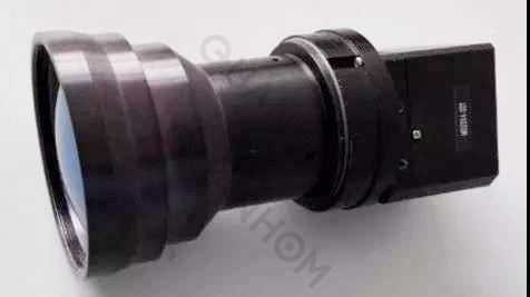
Fig. 2 Prototype of wavefront encoding infrared imaging system of ZnSe phase plate
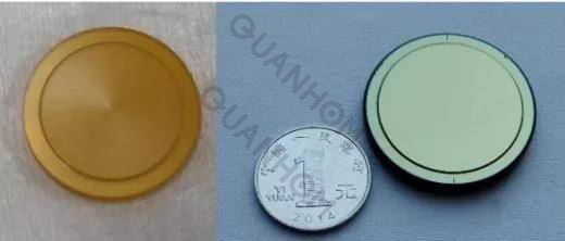
Figure. 3 Uncoated (left) and coated (right) ZnSe phase plates
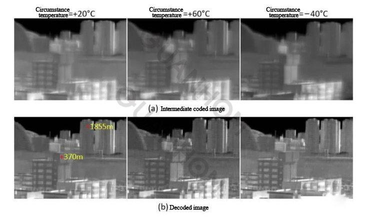
Fig.4 The athermalization experimental results of the prototype ZnSe phase plate wavefront coding infrared imaging system
In 2017, the project team developed a wavefront-encoded infrared imaging system with an athermal temperature range of 110℃ (see Figure 5, left), and its optical encoding uses germanium (Ge) tertiary phase plate (see Figure 5, right) , its working temperature range is –40℃~+70℃, focal length f=65mm, F-number is 1.0, the field of view is 6°×8°; the detector is an uncooled infrared detector with a 320×240 area array, The pixel size is 38 µm, and the working band is 8~12µm.
Figure 6 shows the effect of two sets of decoded images at room temperature, Figure 7 shows the high and low temperature experimental device used for athermalization verification, and Figure 8 shows the experimental results on the target. Figure 9 shows the experimental results for the exterior. Relevant research results have been reported in international journals (Infrared Physics & Technology, 2017, 85, 157-162; Journal of Optics, 2016, 18: 075703).
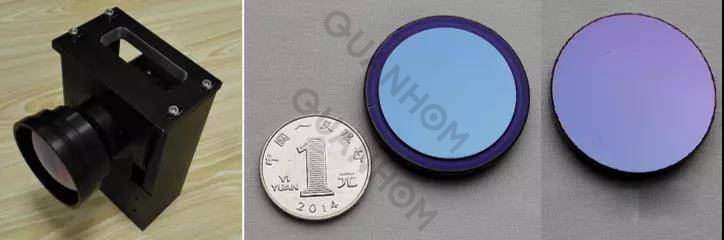
Fig. 5 Prototype of wavefront encoding long-wave infrared imaging system and GE material optical phase plate

(a) Group 1 experiment. Intermediate encoded image (left) and decoded image (right)
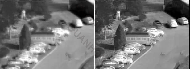
(b) Group 2 experiments. Intermediate encoded image (left) and decoded image (right)
Figure. 6 Two sets of experiments of the prototype wavefront coding infrared imaging system under normal temperature conditions
The project team used the above-mentioned germanium material phase plate wavefront coding infrared imaging system prototype to carry out a comparison experiment with the ordinary infrared imaging system. Three advantages:
(1) Works well in a wide temperature range of 110℃;
(2) The focal depth of the imaging system is expanded by 15.2 times;
(3)The average structural similarity (MSSIM) index value of the decoded image and the sharply focused infrared image is higher than 0.85.
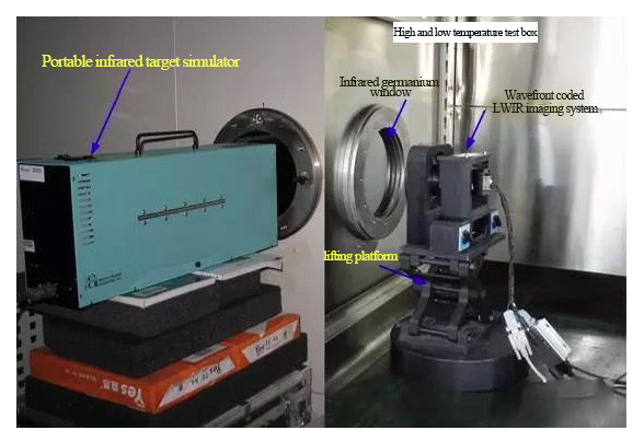
Fig.7 Experimental setup for athermalization verification of infrared imaging system prototype
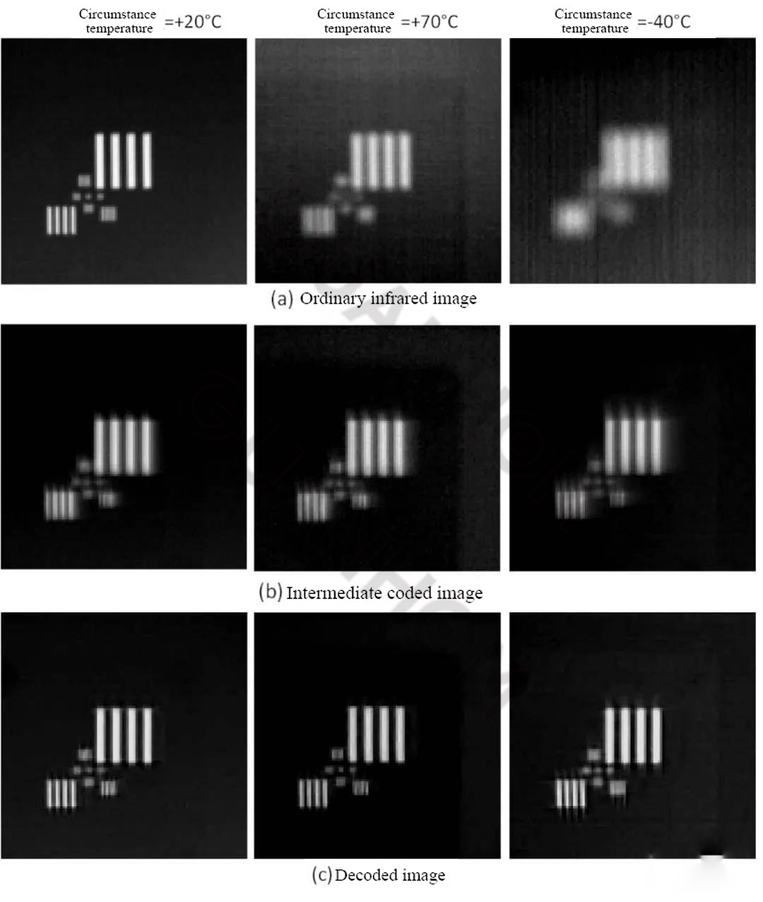
Fig. 8 Target experiment results of athermalization verification
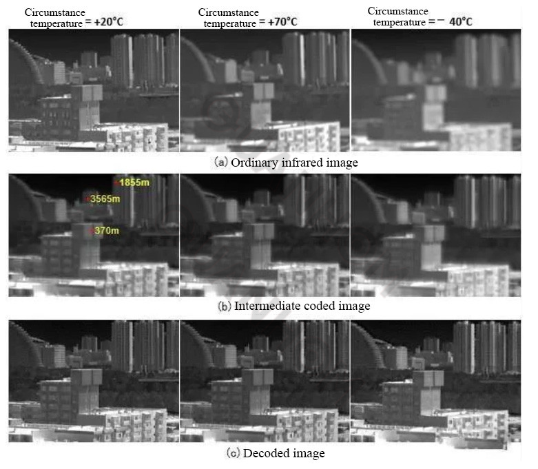
Fig. 9 The athermalization experimental results of the prototype wavefront coding infrared imaging system (phase plate containing germanium material)
In 2017, the project team developed a two-lens wide-field wavefront-encoded infrared imaging system (see Figure 10). The optical phase plate is a double-sided type (aspherical in the front, cubic in the back, see Figure 11), and the material is Ge. Its working field of view is 25° in a full field of view, and its working temperature range is -20℃~+70℃; its detector is an uncooled infrared detector with a 640×512 area array, and the pixel size is 17µm. The band is 8~13.5µm.
Figure 12 shows the site where the field-of-view test experiment was carried out, and Figure 13 shows the results of the athermalization verification experiment. Relevant research results have been reported in international journals (Infrared Physics & Technology, 2017, 87: 11-21).
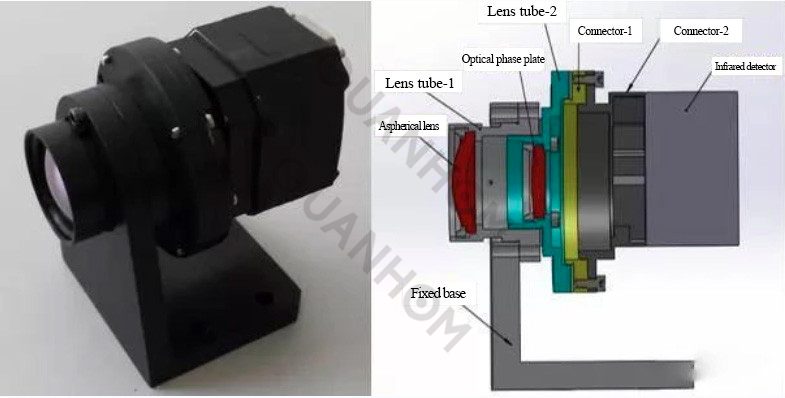
Figure. 10 A prototype of a wide-field wavefront-encoded infrared imaging system. Left: physical map; right: optomechanical model
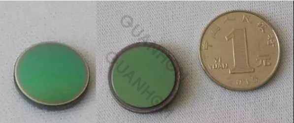
Fig. 11 Aspheric surface (left) and cubic surface (right) of double-sided phase plate
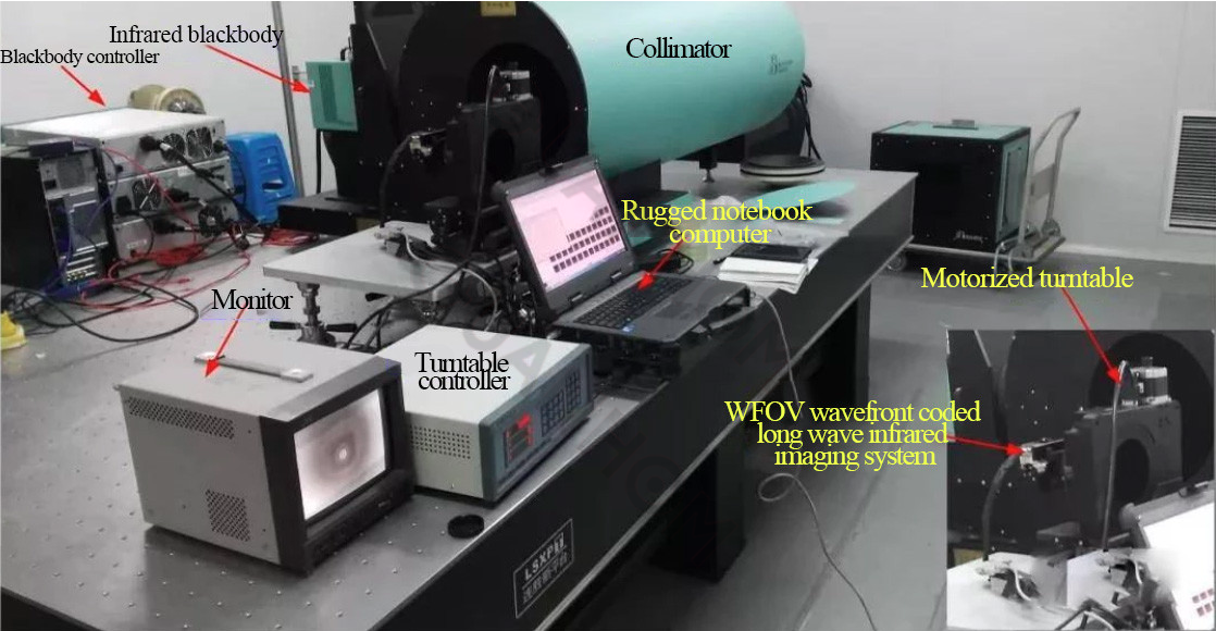
Figure. 12 Field of view test experimental setup of the prototype wide-field-of-view wavefront-encoded infrared imaging system
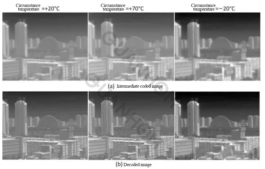
Fig. 13 The athermalization experimental results of the prototype of the two-lens wide-field wavefront coding infrared imaging system
In 2020, the project team theoretically analyzed the influence mechanism of the optical point spread function (PSF) digital deviation in the wavefront coding infrared imaging system on the decoded image quality and made a quantitative evaluation with the mean structural similarity (MSSIM) index. The experimental setup (see Figure 14) and method of the measured wavefront-encoded PSF image is given.
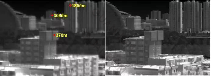
Figure 15 is an example of the measured PSF image. Figure 16 shows the effect of two sets of decoded images using the measured PSF images, showing the effectiveness of the measured PSF. Relevant research results are reported in international journals (Journal of Optics, 2020, 22: 025703).
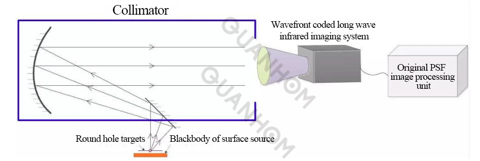
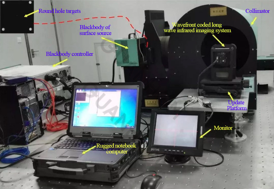
Figure. 14 Schematic diagrams of the measured PSF image (top) and experimental setup (bottom)
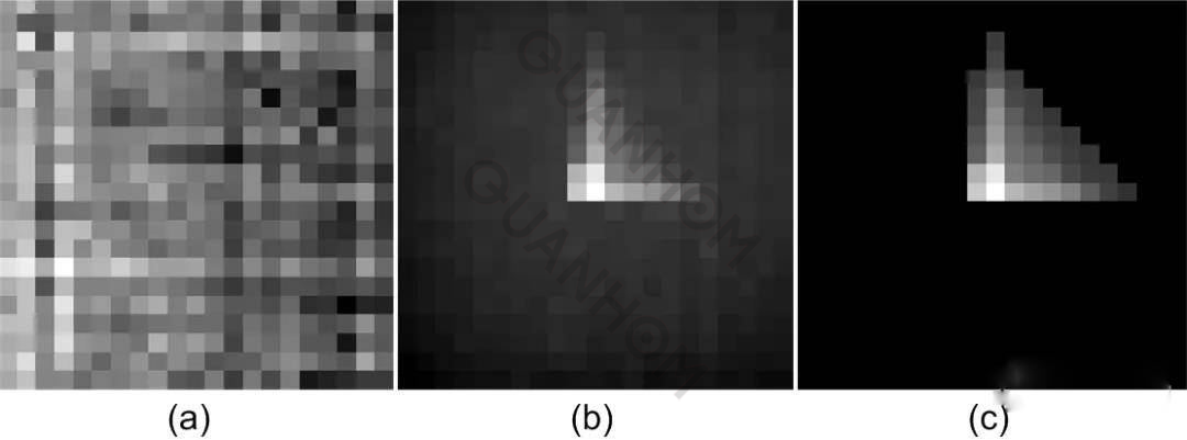
Figure. 15 illustrates the flow of processing raw PSF images. (a) original PSF image; (b) non-uniformly corrected PSF image; (c) corrected PSF image
(a) Group 1 experiment. Intermediate encoded image (left) and decoded image (right)

(b) Group 2 experiments. Intermediate encoded image (left) and decoded image (right)
Figure. 16 The measured PSF image is used to decode the intermediate coded image of the outdoor scene
To sum up, the current research on wavefront coding infrared imaging technology at home and abroad mainly focuses on using wavefront coding imaging technology to expand the depth of field, improve the temperature adaptation range of the infrared imaging system, reduce the aberration of the infrared optical system, and reduce the entire infrared imaging system. The volume, weight, and cost of optical systems, focusing on simulation and experimental verification of basic principles.
At this stage, the wavefront coding infrared imaging technology has the following problems to be solved:
(1)The existing wavefront coding imaging technology is difficult to apply to the athermalization design of the zoom infrared optical system, which is a difficult problem to be solved. In the design process of the wavefront coding infrared imaging system, parameters such as ordinary infrared optical system and athermalization temperature range need to be considered.
The continuous zoom of the infrared optical system will increase the difficulty of designing the parameters of the optical phase plate, and the continuous zoom of the infrared optical system will results in continuous changes in the optical PSF, increasing the difficulty of keeping the digital decoding core "matched" with the optical encoder in the digital decoding design. Continuous zoom poses challenges to the design of both optical phase plates and digital decoders.
(2)The imaging quality evaluation of wavefront coding is a basic problem faced by the technical application. In the wavefront coding infrared imaging system, the "mismatch" between optical coding and digital decoding in the information space causes "artifacts" in the decoded image, which reduces the resolution of scene details. Applications have varying degrees of impact. Therefore, combining the specific application-oriented decoding image quality evaluation is a difficult problem to be solved.
In the future, wavefront-encoded infrared imaging technology is expected to be applied in the aerospace field:
(1) Wavefront coding imaging technology is used for athermalization, lightness, and miniaturization of space infrared cameras.
For the infrared optical system with a large aperture and long focal length, the defocus amount is more sensitive to the temperature change, and the wavefront coding improves its volume, weight, and cost more obviously. The existing wavefront coding infrared imaging system mainly adopts a transmissive structure. For large aperture, long focal length, and catadioptric infrared imaging systems, the wavefront coding technology is used to reduce the volume, quality, and cost, which is also worthy of in-depth study.
(2) Wavefront coding imaging technology is expected to be used in infrared seeker anti-laser anti-jamming.
The strong laser will damage the target surface of the detector, causing dazzling and blinding. The optical encoder can spread the light spot, greatly weaken the energy convergence, and play a protective role.
The new technology, new method, and new technology of wavefront coding infrared imaging technology in the future are also worthy of in-depth exploration and research:
(1) The lamination process of optical coding components is worth exploring and researching. The production process of the optical phase plate is completed by the single-point diamond turning process, and the cost reduction is limited. With the popularization of the lamination process for domestic infrared lenses, combined with the processing error compensation method in the back-end digital decoding process, the lamination process is used to make the wavefront. Optical phase plates for encoding infrared optical systems deserve further study.
(3)The introduction of deep learning into wavefront coding infrared imaging technology is worth exploring. The digital decoding processing of the existing wavefront coding infrared imaging system usually adopts the model method, which generally has the defects of serious artifacts and noise amplification. The deep neural network has good nonlinear mapping fitting ability, and the decoding process is based on deep learning. It is expected to obtain better-decoded image effects.
(4)Wavefront coding super-resolution infrared imaging technology is worth exploring and researching. Internationally, there have been reports on the use of wavefront coding technology to improve visible-light cameras, but there have been no public reports on improving the imaging resolution of infrared cameras.
Explore and research new mechanisms, new methods, and new technologies to improve the imaging resolution of infrared cameras by using wavefront coding. It has theoretical and applied value. In the future, it is also a prospective research direction to expand the wavefront-encoded athermalized infrared imaging system to a wavefront-encoded infrared imaging system with super-resolution imaging at the same time.
The infrared thermal imaging lens studied in this paper is designed and manufactured by Quanhom, and can be used for professional experiments and analysis.
With excellent R&D technology and a strict quality inspection system, we have quickly become one of the leading manufacturers of Opto-electromechanical components. We are committed to producing various high-quality thermal infrared lenses (LWIR, MWIR, and SWIR) according to the diverse needs of customers. Our thoughtful one-stop service has also won the unanimous praise and trust of many customers. If you want to buy our infrared thermal imaging lenses, please contact us immediately!
Journal source: Infrared and Laser Engineering, 2022, 51(1): 20210454. DOI: 10.3788/IRLA20210454
about the author:
First author: Shi Zelin
Shi Zelin, Ph.D., researcher of Shenyang Institute of Automation, Chinese Academy of Sciences, director of the Key Laboratory of Optoelectronic Information Processing, Chinese Academy of Sciences, doctoral supervisor of University of Science and Technology of China, and University of Chinese Academy of Sciences. He has been engaged in the research of optoelectronic information technology for a long time and served as the chief scientist of the 973 plan project.
His achievements won 2-second prizes of National Technological Invention Awards in 2008 and 2017, 1-second prize of National Science and Technology Progress Award in 2010, and led his team to win 1 Outstanding Scientific and Technological Achievement Award of Chinese Academy of Sciences in 2016. Authorized more than 50 invention patents and published more than 260 academic papers.
Feng Bin
Feng Bin, Ph.D., is an associate researcher at the School of Automation, Northwestern Polytechnical University. In 2011, he stayed at the Shenyang Institute of Automation, Chinese Academy of Sciences to work in advance. In 2012, he graduated from the University of Chinese Academy of Sciences with a doctorate. In 2018, he was transferred to the School of Automation, Northwestern Polytechnical University. Mainly engaged in wavefront coding infrared imaging, infrared temperature measurement, polarization imaging, target detection, deep learning applications, and other research work.
He presided over more than 10 sub-topics of the National 973 Project, sub-topics of the Innovation Special Zone Project, Shaanxi Provincial Key R&D Program Projects, and Aerospace Science and Technology Fund Projects. Served as a letter evaluation expert of the National Natural Science Foundation of China, an editorial board member of the domestic journal "Applied Optics", a reviewer of the journals "China Laser" and "Optical Journal", and won the outstanding reviewer of China Laser Magazine in 2017 and 2019; international journals Reviewer for Optics Letters, Journal of Optics, Applied Optics.
Feng Ping
Feng Ping, a master's student of the School of Automation, Northwestern Polytechnical University, has been engaged in the research of wavefront coding infrared imaging technology since 2020. She has participated in the Aerospace Science and Technology Fund, the Open Fund of the Key Laboratory of the Chinese Academy of Sciences, and the emergency research project of the New Coronary Pneumonia Epidemic Prevention and Control of Northwestern Polytechnical University.