

Design and Realization of Light and Small Long-wave Infrared Optical System
The long-wave infrared 8-14 μm spectral region is not only the atmospheric window but also the concentrated band of thermal radiation energy of objects at room temperature.
The passive photoelectric system working in this area mainly detects the thermal radiation of the target source itself. It can work all day, is passive, and has good concealment. It can be used in the military for target reconnaissance, capture, tracking, etc. It can also be used in applications such as forest fire warning, night security surveillance, and search and rescue.
Long-wave infrared detection instruments for remote sensing applications are usually mounted on platforms such as satellites, aircraft, and UAVs. There has been a surge in research on UAV applications in recent years.
The United States continues to promote the use of UAV-borne multispectral imaging sensors. In 2018 In March, the U.S. Marine Corps first deployed a small quad-rotor instant-eye UAV with a flying height of 3 657.6 m, equipped with three infrared photoelectric sensors and one forward-looking thermal infrared sensor.
In July 2018, the Russian company Zala deployed lidar on drones for the first time with the help of lidar’s better situational awareness and faster data collection capabilities. At present, the MEOS photoelectric sensor mounted on the "UAV Dome" of the Israeli company Rafal can achieve target detection with a minimum size of 20 cm2 at a distance of 3.2 km and an instantaneous field of view of 0.14 mrad.
Optoelectronic payloads suitable for UAVs have developed rapidly in function and performance and can obtain high-quality images and data in real-time day and night, which greatly improves the capabilities of reconnaissance, surveillance and target capture.
However, due to the limited carrying capacity of UAVs, high payload performance, lightweight and small size are required, and at the same time for commercial and large-scale batch applications, it also has the characteristics of low cost.
Due to the advantages of high-precision and controllable attitude in a wide range, optoelectronic pods are widely used on UAV platforms, while optoelectronic instruments installed in optoelectronic pods have more stringent volume and weight constraints, and their optical systems need to be considered. Lightweight and compact design.
With the development trend of miniaturization and lightweight of infrared optical systems, the surface shape of optical lenses is often more complicated. Higher requirements are also placed on the microscopic quality of the optical surface of infrared hard and brittle materials such as germanium and zinc selenide.
At present, single-point diamond turning technology has been widely used in the cold processing of infrared optical parts. Under the premise of certain materials and other parameters, the single-point diamond turning accuracy, turning parameters, machine vibration, and methods of machining spherical surfaces can be optimized.
According to the index requirements and platform constraints of the instrument, Quanhom proposes a light, small, and compact catadioptric optical structure that simplifies the main optical form for the application of refrigeration detectors, which is suitable for mass-produced UAV optoelectronic pod long-wave infrared cameras.
This camera's optical design, processing, inspection setup, and imaging experiments will be described in detail below.
1. Platform constraints and index requirements
1.1 Detection method and resource constraints
The optical system is installed in the optoelectronic pod and mounted on the UAV. The instrument has a medium field of view. Through the two-dimensional rotation of the optoelectronic pod, the wide-area target search is realized, the target is found and locked for tracking. As shown in Figure 1, the optoelectronic pod adopts a spherical structure, the radius of the pod is less than 200mm, the diameter of the window is 165mm, the optical space is 320mm×310mm×302mm (including the detector), and the optical-mechanical mass of the camera is required to be less than 2.0 kg (not included). including turntable and electronics).
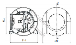
Fig.1 Schematic diagram of detection method
1.2 Indicators related to optical design
In order to improve the detector sensitivity of the instrument, the whole machine uses a cooled area array detector, the pixel size nx×ny is 320×256, the pixel size p is 30μm×30μm, and the optical system design parameters are shown in Table 1.
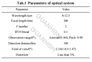
According to the requirements of the farthest detection distance of the instrument, the diameter D of the system is solved to be 150mm. If the F-number of the detector is 2, the system focal length f is 300mm, the instantaneous field of view IFOV=p/f=0.1 mrad, that is, the target resolution at 100 kilometers is 10m, and the field of view FOV is:

That is, the diagonal circular field of view is 2.34°.
2. Optical design
2.1 Selection considerations
Infrared optical system structures include transmissive, reflective, and catadioptric structures. Due to the few optional materials and 100% cold screen matching of the transmission lens group, the front lens has a large diameter and a large volume and weight, but it is relatively easy to process and adjust. It is suitable for small and medium diameters, medium and low resolutions, and large fields of view.
The reflective system has no chromatic aberration, but the field of view is relatively small, and the installation and adjustment are relatively small. Difficult, suitable for medium and large aperture, medium high resolution, small field of view; the catadioptric system has the advantages of the first two, strong aberration correction ability, compact size, can achieve 100% cold screen matching through secondary imaging, for medium and large caliber, medium and high resolution, the medium field of view occasions.
Given the above comparative analysis, combined with the requirements of the UAV loading platform for the volume, weight resources, and detection distance of the instrument, the system selects a catadioptric optical structure, and at the same time, takes into account the cost and cycle of processing, inspection, and assembly, for the application of refrigeration detectors, a catadioptric optical structure that simplifies the main optical form is proposed in the optical design.
2.2 Initial structure
In many references, the optical system of the catadioptric infrared camera adopts the structure of the two-mirror main system and the correction lens group. The optical design usually solves the initial solution of the two-mirror structure first, and then adds the lens group for optimization.
Set the obscuration ratio and the type of aberration to be corrected, set the corresponding aberration coefficient to zero, solve the curvature radius, conic coefficient, and center interval of the primary and secondary mirrors, and then zoom in, on the initial construction of the two-mirror system can be carried out.
In the commonly used catadioptric system, the main optics is a cassette structure that corrects spherical aberration and coma aberration, and the primary mirror and secondary mirror are both hyperboloids.
A correction lens group is added behind it, and the correction lens group is generally spherical. The system simplifies the commonly used fold-back system considering the volume and weight, the difficulty of assembly and adjustment, the development cost, and the use environment.
The simplified catadioptric system is composed of a Newton folded main system and a correction mirror group. The main mirror of the main system is simplified to a paraboloid, the secondary mirror is simplified to a plane mirror, and the secondary mirror has no power only for the folded optical path, which is added to the correction mirror group. We can add aspheric to correct for off-axis aberrations.
The simplified schematic diagram of the optical path of the Newton folded primary system is shown in Figure 2, where h1 and h2 are the heights on the primary and secondary mirrors of the light at the edge of the central field of view respectively.
I2 and I2’ are the object distance and image distance of the secondary mirror, and F1’ is the main Mirror focal length, R01 is the central curvature radius of the primary mirror, R2 is the curvature radius of the secondary mirror, d is the interval between the primary and secondary mirrors, α is the blocking ratio of the secondary mirror, and β is the magnification of the secondary mirror. For the simplified system, the following expressions hold:
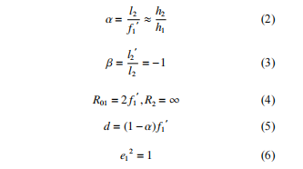
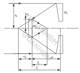
Fig.2 Simplified schematic diagram of the Newton folding main system
The initial structure solution steps of the system are: (1) Assign the power of the main optics and the correction lens, determine f1′, and determine the center curvature radius R01 of the main mirror according to the formula (4); (2) Set the blocking ratio α, according to the formula (5) Solve the interval d of the primary and secondary mirrors; (3) Preliminarily assign the optical power of the correction lens group, and set the object distance of the correction lens group.
The advantages of this design are:
(1) There is no need to design compensation mirrors or holograms to process and adjust the parabolic primary mirror. The installation and adjustment of the main optical system is mainly the stress-free installation of the main parabolic mirror. The detection and adjustment are relatively simple, the development cost is low, and the development cycle is short.
(2) Move the aspheric surface to the lens of the correction lens group, and use the single-point diamond turning technology to process. The processing procedures and costs of the rotationally symmetric aspheric surface and the spherical surface are basically the same, and the surface shape accuracy of the small-diameter lens is high.
(3) The exit pupil of the optical system is behind the correction lens group and is connected to the cold screen of the detector to achieve 100% cold screen matching, reduce the influence of thermal background, and improve sensitivity.
(4) The correction mirror group is between the primary and secondary mirrors, the focal plane of the system is near the primary mirror, and the detector's refrigeration components and installation parts are on the back of the primary mirror, which is beneficial to shorten the camera volume and detector installation.
The above advantages are suitable for rapid batch development of light, small and compact systems.
2.3 Optimal design and results
Input the initial structure into the software. For the sake of simplicity, the correction lens group is divided into positive, negative, negative, and positive powers, and the 19.8mm in front of the detector core (where the cold screen is) is set as the exit pupil (or STOP) of the system.
Edit the advantage function to control the lens thickness, interval, focal length, distortion and image quality, etc., and try to control the entrance pupil to perform ray tracing near the main mirror. The design results are shown in Table 2.
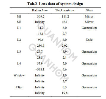
Figure 3 is the optical path diagram of the infrared camera, the primary mirror is a paraboloid, the secondary mirror is a plane, the front surface of mirror 1 and the rear surface of mirror 3 in the correction mirror group are quadric surfaces, and the total axial length of the system is 125mm.
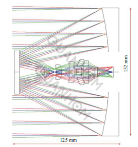
Fig.3 2D layout
As shown in Figure 4, the MTF values of each field of view in the spectral range of 8-12.5μm are close to the diffraction-limited value at the Nyquist frequency, all greater than 0.4; the system distortion is less than 2.8% in the full field of view.

3. Engineering feasibility analysis
3.1 Tolerance analysis
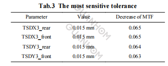
Tolerance analysis is to provide precision control reference values for the machining of optomechanical parts and assembly of components. The system sets the surface shape, surface eccentricity and inclination, element eccentricity and inclination, center thickness and interval of the optical lens, sets the focal plane compensation variable, obtains the most sensitive parameters through Monte Carlo random analysis, and adjusts the sensitive parameters to make Monte Carlo The Lowe analysis resulted in a reduction in correspondence of less than 15%.
The tolerance analysis of the whole system is carried out, and the sensitive tolerance items are listed in Table 3. The surface decentration (TSD) and tilt (TST) of the curved third lens are more sensitive, which should be paid attention to during the optomechanical system development. The remaining unlisted tolerances are more general.
3.2 Analysis of temperature adaptability
Without thermal control, the working ambient temperature of the UAV onboard optoelectronic pod is about –40~60 ℃. However, considering the cost and the volume resources given to the optical system by the optoelectronic pod, the thermal design scheme is: primary thermal control combined with adaptive optical design within a limited temperature range. That is, the temperature in the photoelectric pod is controlled between 15 and 25 ℃ through primary thermal control, (the radial temperature difference is less than 2 ℃, and the axial temperature difference is less than 5 ℃).
In this temperature range, the temperature drift of the image surface of the instrument is required to meet the spatial resolution requirements without focus. In this way, the preliminary thermal control is easier to achieve, which not only reduces the pressure on the optical system, but also reduces the cost, and the system performance can meet the loan application requirements.
The correction lens group can effectively dissipate heat difference in the above working temperature range through material matching and optical power distribution and has the characteristics of simple structure and small weight and volume.
The optomechanical material of the main system is made of aluminum, the correction lens group uses four lenses of germanium, zinc selenide, germanium, and germanium, and the lens barrel structure is made of aluminum. The environmental adaptability scheme of the camera is to adopt the primary thermal control and optical adaptability design within a limited temperature range. Weigh the volume resources given by the optoelectronic pod to the optical system, and control the temperature in the optoelectronic pod between 15 and 25 °C through primary thermal control.
The main system mirror blank and camera structure are all made of aluminum, and the camera mass is 1.8 kg (including detector). The reference temperature is set to 20 °C, the radial temperature difference is 2 °C, and the axial temperature difference is 5 °C. The optical transfer functions are all greater than 0.3 at the Nyquist frequency, as shown in Fig. 6(a). In addition, the transfer functions corresponding to the temperature points at both ends of the software simulation at 15 °C and 25 °C are all greater than 0.33, as shown in Fig. 6(b) and (c).
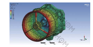
Fig.5 Finite element analysis model
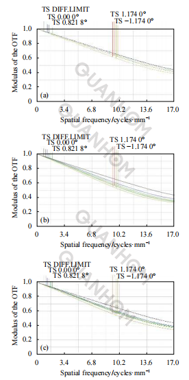
Fig.6 Transfer function simulation
4. Processing inspection, assembly and imaging experiments
4.1 Optical processing inspection
The mirrors in the main system and the lenses in the correction mirror group are processed by single-point diamond turning technology (SPDT) [12−14]. The primary mirror and secondary mirror in the primary optics are made of optical aluminum T6061, as shown in Figure 7.
After turning and polishing, the surface shape accuracy is further improved, both of which are better than λ/20@632.8nm; The lenses are all rotationally symmetrical spherical or aspherical surfaces. The mirror blank is made of germanium or zinc selenide. The infrared material with small aperture is easy to process, and the surface shape accuracy is better than 1/20λ@632.8nm.
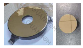
Fig.7 Primary and secondary mirrors
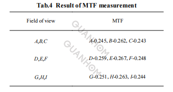
9 points were selected on the holographic plane, and the MTF was calculated according to the formula (7) according to the DN value of the target image. The detector transfer function is calculated at 0.6, and considering that the slit is slightly wider, the optical MTF of the system can reach 85% of the design value, which is within the acceptable range.
4.3 Exterior imaging experiment
The system location imaging experiment site is on the ninth floor of the building, and the experiment time is a winter evening. The system imaging diagram is shown in Figure 10. Point a in the scene is a residential building at a distance of 2 km, with clear outlines and precise details; point b is a residential building pipeline at a distance of 1 km, with a scale of about 0.1 m, which can be clearly distinguished; the black dot at c in the lower-left corner of the image is the outdoor unit of the air conditioner in winter, and the black part in the upper right corner is the sky.
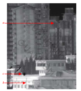
Fig.10 Scene image
5. Conclusion
Aiming at the infrared detection requirements of UAV-borne miniature optoelectronic pods, a long-wave infrared optical imaging system for refrigeration detector applications was designed and developed. A Newtonian folded structure replaces the commonly used cassette structure, and the image quality correction of a larger field of view is realized by simplifying the structure of the main telescope and adding an aspherical surface to the correction mirror group.
The main system adopts an all-aluminum optomechanical structure design, and the optical components of the whole system are processed by single-point diamond turning technology, which reduces the difficulty of processing, assembly and development and development costs; 100% cold screen effect design is realized through secondary imaging, which reduces the infrared thermal background, which is beneficial to improve the sensitivity of the system. The optical system has the characteristics of small size, compact structure and excellent image quality.
The system's final installation and commissioning test results show that the image quality meets the design expectations and meets the requirements of the project's technical indicators. This paper has certain reference significance for designing and developing a compact infrared optical system for infrared detection similar to the UAV-borne miniature optoelectronic pod.
We are an experienced manufacturer of Opto-electromechanical components, dedicated to providing users with a variety of high-quality infrared thermal imaging lenses. We take customers’ needs as the first priority and comprehensively control the quality of our products. For this reason, we are equipped with a strict quality inspection system to control the design, manufacturing, and export of the products. If you are interested in our infrared thermal imaging lens, please get in touch with us immediately!
Authors: Hao Siyuan, Xie Jianan, Wen Maoxing, Wang Yueming, Yuan Liyin
Received date: 2020−01−17; Revised date: 2020−02−08
Journal source: Vol.49 No.9 Infrared and Laser Engineering Sep. 2020
References:
[1] Cao Yinqi, Qi Yuan, Cheng Gang, et al. Development and key technologies of small photoelectric pods for military drones [J].Aircraft Missiles, 2019(3): 54-59. (in Chinese)
[2] Zhou Feng, Liu Jianhui, Guo Jun, et al. Development analysis of foreign airborne infrared early warning systems [J]. Laser and Infrared, 2017, 47(4): 399-403. (in Chinese)
[3]Li Lei, Xu Yue, Jiang Qi, et al. Overview of foreign military UAV equipment and technology development in 2018 [J]. Tactical Missile Technology, 2019(2): 1-11. (in Chinese)
[4]Gao Sifeng, Wu Ping, He Manali, et al. Estimation of working distance of infrared system under complex atmospheric conditions [J]. Infrared and Laser Engineering, 2008, 37(6): 941-944. (in Chinese)
[5] Shi Guanghui. Using Gaussian optics and third-order aberration theory to find the initial solution of a zoom objective lens [J]. China Optics, 2018, 11(6): 1047-1060. (in Chinese)
[6] Chen Li, Liu Li, Zhao Zhicheng, et al. Optical system design of long focal length coaxial four-mirror [J]. Infrared and Laser Engineering, 2019, 48(1): 0118002. (in Chinese)
[7] Bai Yu, Liao Zhiyuan, Li Hua, et al. Design and analysis of athermal imaging system for folded reflective medium wave infrared detection [J]. Infrared and Laser Engineering, 2015, 44(2): 407-412. (in Chinese)
[8] Jiang Kai, Zhou Sizhong, Li Gang, et al. Thermal-free design of a folding mediumwave dual infrared field of view zoom system [J]. Infrared and Laser Engineering, 2013, 42(2): 403-407. (in Chinese)
[9] Xiao Guanghui, Hao Peiming. Design of a newton's optical system with no power correction plate [J]. Applied Optics, 2008, 29(5): 753-757. (in Chinese)
[10] Mu Yongji, Mao Yijiang, Hu Mingyong. Design of an off-axis parabolic mirror aberration correction mirror group [J]. Acta Optica Sinica, 2014, 34(6): 227-232. (in Chinese)