

The Working Principle and Composition of Infrared Sensor
The Working Principle and
Composition of Infrared Sensor
1. The working principle of infrared sensor
After the infrared radiation of the target and the
background passes through the objective lens, it is imaged on the focal plane
of the detection component. The infrared detection component converts infrared
radiation into electrical signals, and preprocessing circuit through the
infrared signal. After the infrared signal is subjected to Correlated Double
Sample (CDS), electronic filtering, and A/D conversion, NUC, defect elimination
and synthesis sorting are performed. Then, the parallel digital signal is sent
to the potential target processing unit through a certain distance transmission
line for further processing.
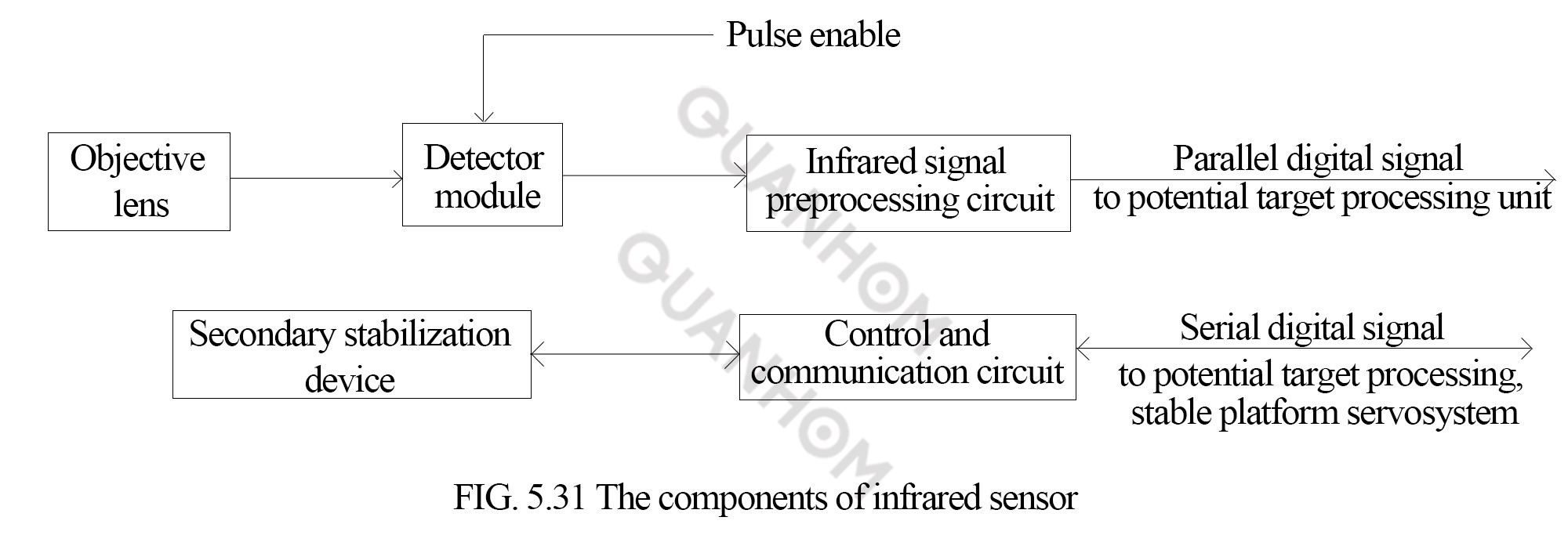
2. The components of infrared sensor
The infrared sensor is composed of objective lens
(infrared optical system), infrared detector module, infrared signal
preprocessing circuit, secondary stabilization device and control and
communication circuit. It is shown in FIG. 5.31.
2.1 Objective lens
The objective lens of the infrared sensor has high
requirements on imaging quality and optical efficiency, and the classical
optical design cannot guarantee the optical efficiency of the objective lens.
Hence, the objective lens should be designed as an aspherical transmission
optical system. The design is made of a variety of materials to correct the
chromatic aberration in the working band.
2.2 Infrared detection
components
An infrared detection component is consist
of the following parts:
(1)ID TL005 288×4 LWIR IDDCA component.
(2)Detector clock pulse generator circuit: generates the pulse signal needed to
ensure the normal operation of the detector.
(3)Detector bias circuit: generate the bias voltage required by the normal
operation of the detector.
(4)Pulse enable generator circuit, the detector CCD readout circuit pulse
enable signal generated by the Angle measurement system, pulse enable arrival,
clock pulse generator circuit is to generate the CCD required pulse signal.
3. Infrared signal preprocessing circuit
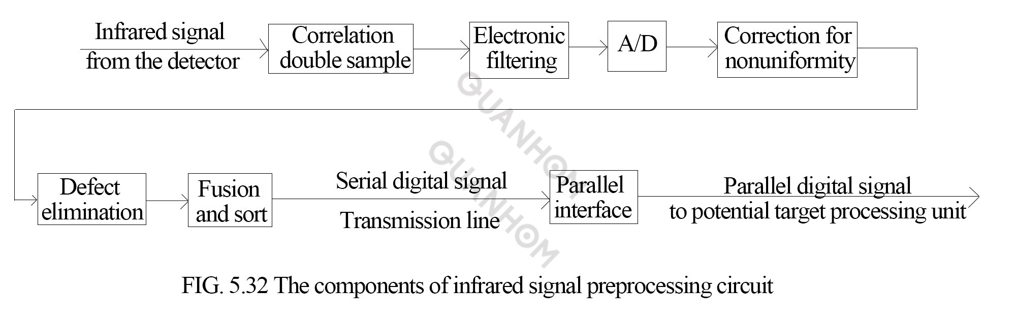
(1) CDS:it is applied to the output signal of the detector to filter out the switching noise generated by the readout circuit of the detector.
(2) Electronic filtering: it can filter the low frequency noise, suppress the
high frequency noise and improve the signal-to-noise ratio.
(3) A/D conversion: it can be used to convert infrared signals into analog/digital quantities, and the quantization level is 12bit.
(4) NUC: it can correct the output signal of each of the 288 channels of the
detector. To ensure that under the action of the same infrared radiation
energy, the non-uniformity of the signals generated by each channel is less
than 0.5%. For detectors with linear response, it is sufficient to perform
two-point correction of responsivity and bias point; for detectors with
nonlinear response, a multi-point piecewise linear approximation algorithm is
required for correction. Since a certain type of infrared system needs to cover
360°, it is not possible to incorporate a temperature reference into the
system. Through research on two-point and multi-point piecewise linear
approximation and scene-based non-uniformity compensation, the work condition
is benign, then general hardware that can perform these three algorithms is
developed.
(5) Defect
elimination: it is replaced by the signal average of two non-defect channels in
the defect neighborhood to achieve defect elimination.
(6) Fusion and
sort: the signal in the previous column is delayed, which is equivalent to the
time between two adjacent columns. After the composite processing of the two
columns, a column of signals is formed to complete fusion and sort.
(7) Parallel interface: it is to output the digital infrared signal, the pixel
synchronization signal and the column synchronization signal to the potential
target processing unit in parallel, and simultaneously receive the column
synchronization signal from the goniometer unit.
4. Control and communication circuits
Functions:
(1) Receive a control signal (including a uniformity correction control signal,
a self-check control signal, and a gain control signal) from the potential
target processing unit, and send a self-check result signal to the potential target
processing unit.
(2) Receive the
platform attitude signal from the stabilized platform servo system.
(3) Control the
secondary stabilization device.
(4) Control the
infrared signal preprocessing circuit.
5. Secondary stabilizing device
The secondary
stabilization device consists of a mirror, a gyro, a servo motor and a drive
circuit. Its function is to perform secondary precise stabilization of the
infrared optical axis.