

What Are Bad Pixels, Ghost Images And Vignetting effect In Infrared Imaging?
This article will introduce several imaging phenomena that often occur in infrared imaging - bad pixels, ghost effect, and vignetting effect. And some methods to solve these defects are given, such as: non-uniformity correction, compensation, SDRAM and FLASH.
1.Bad Pixels
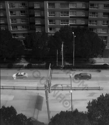
Bad pixels refer to light and dark spots whose coordinates do not change with the target in the infrared image. Bad pixels are also called non-functional pixels (including overheated pixels and dead pixels). Pixels with noise voltage exceeding 10 times the average noise voltage are referred to as overheated pixels (white spots), while pixels with a response rate less than 1/10 of the average response rate are called dead pixels (black spots).
Pixel noise voltage:It is the effective value of the voltage fluctuation of the pixel output signal in the focal plane of a pixel under background irradiation conditions, that is, the total noise of the background image signal.
Pixel response rate:It is the output signal voltage generated by the focal plane per unit of radiation power within the dynamic range under a certain frame period or line period.
(Scanning from left to right is often called horizontal scanning or line scanning while scanning from top to bottom is usually called vertical scanning or frame scanning)
Causes of Bad Pixels
Defects in the array process formed by each light-collecting point on the infrared detector, or errors in the optical signal conversion process, will lead to information errors in some pixels on the image, resulting in inaccurate pixel values in the image. These defective pixels are imperfections in the image.
In addition, prolonged usage of infrared imaging in high-temperature environments can lead to an increase in the number of defective spots on the infrared detector. This can result in a degradation of image clarity, integrity of infrared thermal imaging, and accuracy of infrared temperature measurement.
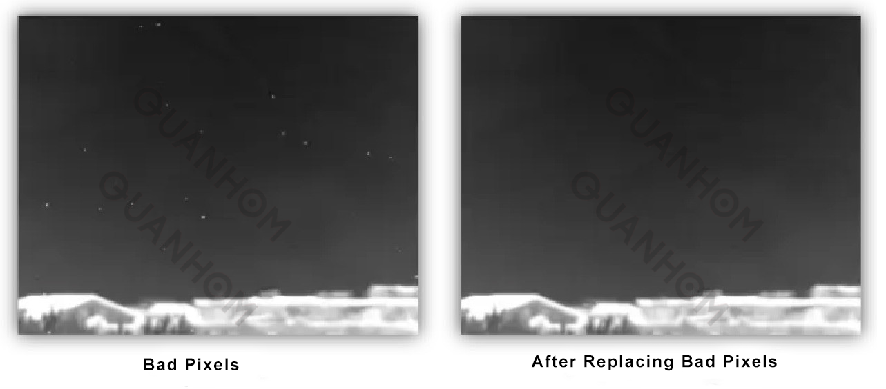
Commonly used bad pixel replacement methods:
left point replacement, upper point replacement, neighborhood median or mean replacement, etc.The principle of bad pixel removal is to replace the pixel value of the bad pixel with the surrounding pixel values. You need to determine the location of the bad pixels in an image and use a calibrated infrared lens to capture blackbody images at different temperatures. The response of the bad pixels to temperature is obviously different from that of normal pixels. Then mark the coordinates of these points and use the surrounding pixels to replace them.
In actual operation, using mean replacement is less effective than using the median of surrounding pixels. because many infrared detector bad pixels tend to cluster together, meaning a bad pixel may have other bad pixels around it. Using median replacement can reduce the impact of surrounding bad pixels on the replacement effect.
2.Ghost Images
Ghost Images refer to bright or dark lines that appear in infrared images and do not change with the target, which appears with faint halos.
Cause:It is caused by the uneven response rate of the detection element of the infrared detector to infrared radiation.
Characteristics of ghost images:The intensity and detail vary with the scene and weather, but the overall shape is consistent on the same detector.
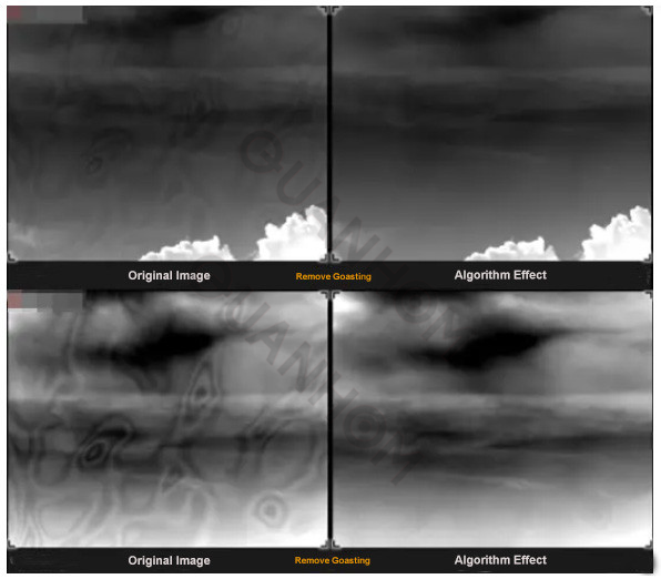
Calibration method:It can be solved by a two-point calibration on site. Generally, during on-site calibration, aim at a low-temperature target such as a clean, cloudless sky and press the designated compensation key; then aim at a relatively high-temperature target (you can choose the closed lens cover) and press a compensation key. After the compensation is completed, the system will automatically calculate the correction coefficient K value based on the background collected by the compensation and perform a two-point correction to eliminate ghosting.
Background:Generally refers to the relevant values generated by the natural environment itself without external human interference.
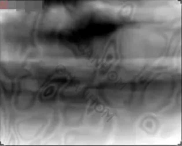
3.Vignetting effect
Factors such as FOV switching, focus adjustment, ambient temperature, shock and vibration of the thermal imaging camera will cause obvious changes in the non-uniformity introduced by the optical system, which causes the output image of the thermal imaging camera to appear black in the center and bright around the edges and corners of the screen. The phenomenon is called Vignetting effect.
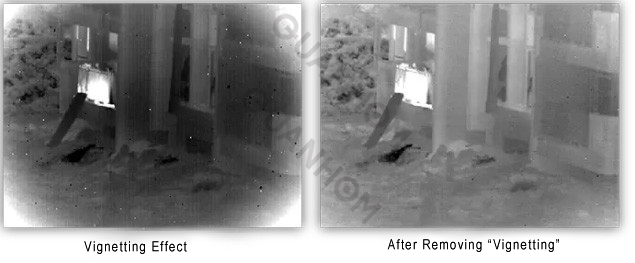
During the process of use, the temperature of the optical system barrel increases, causing the edge temperature of the lens to be higher than the center, or the thermal radiation of the barrel reaches the detector through the optical lens, causing the gray level to gradually increase from the center to the edge of the image. As the instrument is used longer, the lens barrel becomes hotter and the vignetting effect. becomes more severe.
A method of suppressing the "vignetting effect" of real-time infrared images, which is characterized by the following steps:
Step 1: Turn on the infrared thermal imaging camera, wait until the image is stable, about 5 minutes, and complete an image non-uniform correction;
Step 2: After completing the step 1, wait for about 15 minutes until the vignetting effect appears, and collect the vignetting effect image for the uniform heat radiation scene;
Step 3: Through statistical distribution of histograms, it is obtained that the point (x0, y0) closest to the center of the image in the relatively dark image pixels is used as the image center of the vignetting effect;
Step 4; According to the resolution and formula of the image
Dmax= max(√(〖〖(x-x0)〗^2+(y-y0)〗^2 )), Calculate the value Dmax, Dmax is the farthest point from (x0, y0) among all pixel points;
Step 5: According to the mathematical model g(x, y) =a×r2+b×r4, where r is the mathematical model related to the image position, the step size for a and b is 0.1, and the range is [-2, 2], iteratively solve g(x, y), and then calculate the value Ilight from Ilight=Iin×g (x, y), where Iin is the original image data collected in real time, Ilight is the additive noise that needs to be required, and Iout is the original image; Use Iout=Iin-Ilight and D(Iout)=∑|Iout-Iideal| to solve for the value D(Iin). D(Iout) is the variance between the ideal output image and the actual image output. Compare the value D(Iin) obtained from each group of a and b, and record the combination of a and b with the smallest value D(Iin);
Step 6: Use the image vignetting effect center (x0, y0) obtained in step 3, the Dmax calculated in step 4, and the combination of a and b when D(Iin) is minimized in step 5 to calculate the Ilight of different scene images in real time. Use lout = Iin-Ilight to suppress the image vignetting effect in real time.
4.Prevention and Improvement Measures
·Non-uniformity correction
Due to the limitations of the infrared detector manufacturing process, each detection element of the infrared detector has a different response rate to infrared radiation. The above-mentioned ghosts and bad pixels will appear on the imaging surface, affecting the imaging quality of the thermal imaging.
Different pixels of the infrared focal plane array have different video output signal amplitudes under the same uniform incident radiation. This is the so-called non-uniformity of the infrared focal plane array response.
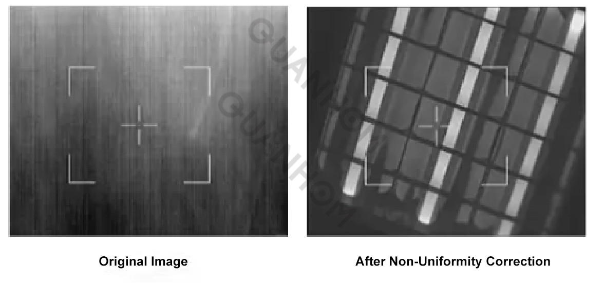
Non-uniformity correction refers to a technical means that effectively reduces the non-uniformity of the detector's response rate (i.e. the inherent spatial noise of the detector) and improves the imaging quality of the thermal imaging.
Spatial noise refers to the difference between the output signals of different pixels when a thermal imaging camera observes a target. Spatial noise can also be divided into low-frequency spatial noise (non-uniformity noise) and high-frequency spatial noise (fixed pattern noise FPN).
After non-uniformity correction, the image of the thermal imaging camera is uniform, ghosts and bad pixels disappear, and the imaging effect is significantly improved, which can greatly improve the observation ability of the thermal imaging camera.
Commonly used correction methods:one-point correction, two-point correction, multi-point correction, etc.
One-point correction method: a method that can correct the output signals of each pixel to be consistent. This approach is to correct the response values of different pixels to the same response value under the same intensity of light radiation, because they are under the same illumination. It can be the average value of the signal at this time or the maximum value under this condition.
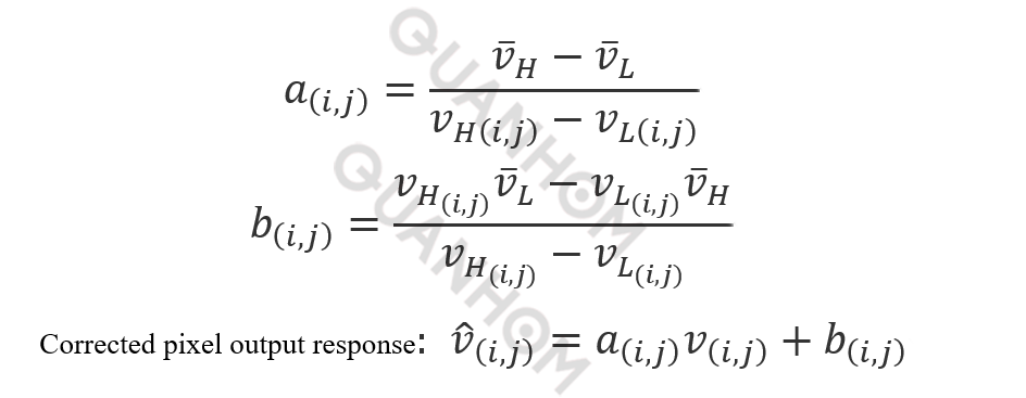
Two-point correction method is one of the commonly used correction algorithms. The implementation method is that take the blackbody radiation conditions at two temperatures as the calibration points, use the detector to obtain a uniform infrared radiation image when the radiation source is a blackbody at the corresponding temperature, and calculate the pixel responses VL(i,j) and VH(i,j) and the average pixel responses ¯VL and ¯VH when the blackbody temperatures are TL and TH. The gains a(i,j) and b(i,j) of each pixel are obtained through the formula:
a(i,j)=¯VH-¯VL / VH(i,j)-VL(i,j)
b(i,j)= VH(i,j)^¯VL - VL(i,j)^¯VH / VH(i,j)- VL(i,j)
Corrected pixel output response: ^V(i,j)= a(i,j) V(i,j)+ b(i,j)
Different from the two-point correction method, which simply uses a linear model to replace the actual response curve, the multi-point method recognizes the response curve. For each segment of the polyline, the two-point scaling method is used to calculate the corresponding an(i,j) and bn(i,j), which are the serial numbers of the polyline segment. After calibration, a series of offset parameters an(i,j), gain parameters bn(i,j), and pre-correction pixel responses corresponding to the line segment endpoints are stored for correction operations. During the correction operation, firstly determine the interval based on the pre-correction response of the pixel, find the an(i,j) and bn(i,j) corresponding to the interval, and calculate the corrected pixel output response ^V(i,j).
Compensation
Compensation is performed to obtain the raw data required for non-uniformity correction. In order to obtain an ideal infrared image during the actual operation of the thermal imaging camera, it is recommended that the user perform compensation operations on the thermal imaging camera when it is just turned on or during long-term operation.
Compensation method: The compensation target can select different objects with uniform temperature according to the on-site environment and target characteristics. Then aim the thermal imaging camera towards the uniform compensation target, and save the original imaging data at this time as the background data required for non-uniformity correction.
Compensation target: Objects with uniform temperature; A clean, cloudless sky; Thermal camera’s built-in shutter.
·SDRAM and FLASH
The background image collected when the thermal imaging performs compensation, the correction coefficient generated by non-uniformity correction, bad pixel correction data, and some control parameters required for the normal operation of the machine, etc., all these data are stored in the memory storage FLASH inside the machine. After the thermal imaging camera is turned on, it automatically transfers the data in FLASH into the machine's memory SDRAM. The data loaded in the SDRAM disappears automatically after the thermal imaging camera is turned off.