

Integrated Opto-mechanical-thermal Analysis of Infrared Lenses
For a high-precision optical system, its optical performance is largely affected by external mechanical loads and ambient temperature, and the interaction between them ultimately determines the performance of the entire optical system. Especially for infrared optical systems, the typical operating temperature in military applications is -40°C ~+60°C.
Under different temperature conditions, due to the inconsistency of the thermal expansion coefficients of the optical lens and the frame structure material, it will cause the deformation of the optical element, and the refractive index of the optical material will also change with temperature, which will lead to the change of the performance parameters of the optical system and cause the image quality to decline or even not work properly. Therefore, it is necessary to consider the infrared system to work in a wide temperature range when designing, which requires an integrated design of light, machine, and heat.
For high-precision optical instruments, its development covers multiple disciplines such as optics, mechanics, electricity, and heat. When designing, it is necessary to fully consider the impact of one discipline on other disciplines' related sub-systems.
The photomechanical and thermal integrated analysis method is currently the most effective method for the design and analysis of optical instruments. It starts from the point of view of system engineering, comprehensively considers the relationship between the optical system, mechanical structure system, and the external thermal environment, and uses CAD/CAE technical means to realize optic.
The optimal design of the instrument system is currently mainly used in the design and analysis of space optical instruments but is rarely used in general infrared optical systems. The method and analysis of the optical-mechanical thermal integration of the infrared lens are as follows.
1. Optical-mechanical-thermal integrated analysis method
The integrated analysis method is currently the method commonly used internationally to solve interdisciplinary problems. Each discipline uses its own analysis software to solve the problems of the discipline. In order to be able to accurately predict the performance of the system, each discipline must be able to exchange data, so that the results of analysis and processing in one discipline become the source data for calculations by another discipline. Transmission integrates several independent analysis software into one. Figure 1 shows the process of optical-mechanical-thermal integrated analysis.
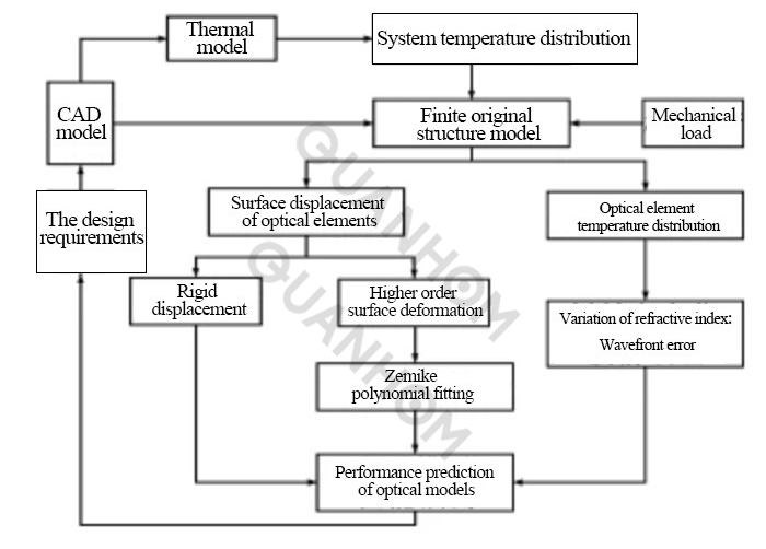
Fig. 1 Flow chart of integrated optical-mechanical thermal analysis
First, build a screen prototype of the optical instrument based on the results of the optical design, and then build a thermal model to obtain the temperature distribution of the system. Load the obtained temperature distribution as a body load to the structural finite element model for mechanical analysis.
By processing the deformation value, the rigid body displacement and surface shape change of the optical element can be obtained, and the data obtained above and the change of the refractive index of the optical element can be substituted into the optics model, then evaluate the effect of temperature on the performance of the optical system. The whole process is a closed-loop design analysis, through repeated analysis and optimization, the optimal system can be finally obtained.
2. Integrated design of optical-mechanical-thermal in infrared lenses
Infrared optical system requirements: the focal length is 200 mm; F/# is 2.5; 2w is 3.3°; the number of detector pixels is 320×240; pixel size inch is 25μm×25μm, and the working temperature is -40℃~+60℃. For the above requirements, if there are no restrictions, a variety of optical structures can be used.
In fact, the length of the optical system is demanding, so in order to reduce the size and achieve better cold diaphragm matching of the system, the infrared lens is designed with a second imaging method. Firstly, put the human pupil on the first surface, and pass the front lens group into a primary image plane, and then the rear lens group will focus the primary image plane on the focal plane, and image the human pupil on the cold light bar of the system, namely the exit pupil and detection of the system. The cold diaphragms of the devices are overlapped, and the optical system shown in Figure 2 is designed.
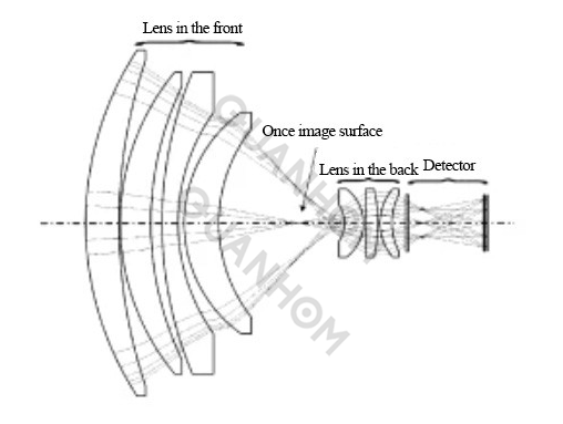
Fig. 2 Optical layout
The front lens of the system is composed of 3 Si lenses with positive refractive power and 1 Ge lens with negative refractive power. The 3 Si lenses are mainly used to focus light and correct spherical aberration, while the Ge lenses are mainly used to correct chromatic aberration. The rear lens of the system consists of 3 Si lenses. The latter group uses secondary imaging on the middle image plane to jointly correct the chromatic aberration and spherical aberration together with the former group.
The focal length of the entire front lens is 50mm, and the magnification of the rear lens is 4. Therefore, if the image plane moves one unit at a time, the final image plane moves about 16 units. The distance between the front and rear lens groups is very sensitive to the position of the image plane, and the change in the lens interval between the front and rear lenses has little effect on the system performance. Therefore, the distance between the front and rear groups is used as a compensation amount to adjust the image plane position for structural design.
The analysis believes that the use of a single structural material cannot realize the compensation of the interval. Therefore, the bimetal structure compensation scheme is adopted, that is, a combination of structural materials with high and low expansion coefficients is used to adjust the desired compensation amount, which can be calculated the length of the two materials by the following formula:

In the formula: α is the thermal expansion coefficient of the high expansion coefficient material; △T is the change in temperature; l1is the length of the high expansion coefficient material; α2 is the thermal expansion coefficient of the low expansion coefficient material; l2 is the length of the low expansion coefficient material; δ is the compensation amount of the front and rear groups corresponding to the temperature; Δl is the interval between the front and rear groups.
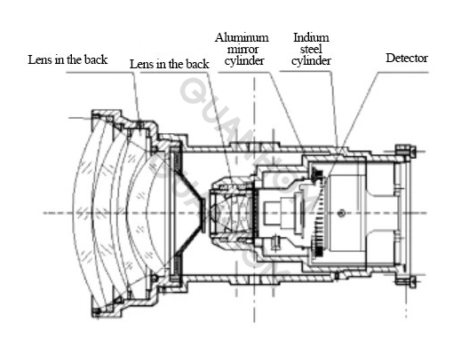
Here, the material with a low expansion coefficient is steel and steel, and the material with a high expansion coefficient is aluminum alloy. Design the mechanical compensation structure shown in Figure 3 to ensure the integrated design of the system.
Among them, the rear group lens is installed on the aluminum lens barrel, and the aluminum lens barrel is installed on the back end of the indium steel barrel. The front group lens is installed on the front end of the indium steel barrel.
The coaxiality of the connecting surface of the indium steel barrel is guaranteed by processing to ensure the entire system. The lens spacer of the front group ensures the distance between the front and rear groups. In the end, the total length of the infrared lens is 146mm, the length of the indium steel tube is 107mm, and the length of the aluminum lens tube is 67.5mm.
3. Thermal integration analysis of infrared lens
3.1 Finite element analysis
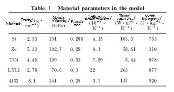
Use finite element analysis software to establish structural analysis and thermal analysis finite element models, as shown in Figure 4. The grid in the figure uses hexahedral and pentahedral elements, with a total of 27,168 nodes and 17,788 elements. The properties of the materials used in the analysis in the figure are shown in Table 1.
In the analysis, the temperature field analysis data is taken as the body load and then the thermodynamic analysis is performed to obtain the deformation value of each lens. Figure 5 is the deformation diagram of each lens when the temperature is 60s℃. It can be seen from the deformation cloud diagram that the change of the interval between the front and rear groups accounts for the main aspect of the deformation, which is also consistent with the design compensation idea.
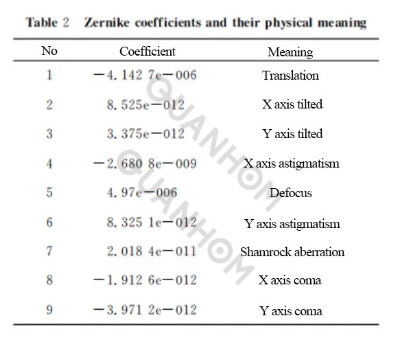
At the same time, extract the nodal displacement of each lens mirror and perform Zernike polynomial fitting to obtain the surface shape change of the optical mirror. The standard Zernike polynomial is used in the analysis. Due to space limitations, Table 2 only lists the first 9 Zernike coefficients, and the corresponding physical meaning can be seen from Table 2. The deformation of the mirror surface is mainly reflected in translation, followed by the defocus caused by the mirror surface deformation, and the other surface shape changes are small.
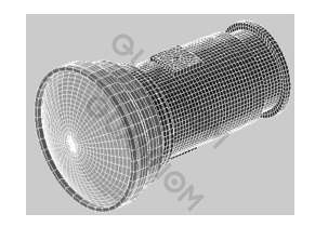
Fig. 4 Finite element model
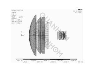
Fig. 5 Displacement of lens at 60℃
3.2 Optical analysis
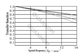
Substituting parameters such as the change in optical interval, the Zernike coefficient of the mirror deformation, and the temperature coefficient of the refractive index of the lens material obtained from the post-thermodynamic analysis into the optical calculation software Code V, to obtain the optical transfer function at each ambient temperature level, as shown in Figure 6.
The results show that the transfer function of this lens in the temperature range of -40℃~+60℃ for each field of view 16 line pairs is greater than 0.5, and the image quality is good.
(a) The transfer function of the lens at 20℃
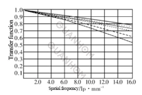
(b) The transfer function of the lens at -40℃
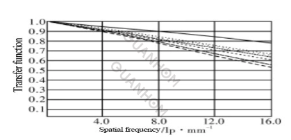
(c) The transfer function of the lens at -60℃
4. Conclusion
For infrared optical systems, the temperature has a great influence on the imaging quality of the optical system. Designed an infrared lens with a wide operating temperature range through the integrated design method of optical, mechanical, and thermal, and further analyzed the deformation of the infrared lens at different temperatures due to the deformation of the mirror surface, the change of the lens interval, and the change of the refractive index temperature coefficient. Factors such as changes in the image quality of the system, the analysis results show that the designed infrared lens has good image quality at -40°C ~+60°C.
The optical-mechanical-thermal integrated design method and optical-mechanical-thermal integrated analysis method used in this paper have important reference values for the design and analysis of similar optical systems.
As an expert in infrared optical lens research for many years, Quanhom can give you some professional guidance to a certain extent. If you want to get a more comprehensive and detailed solution after reading this article, please feel free to contact us.
We are an experienced manufacturer of Opto-electromechanical components, dedicated to providing users with a variety of high-quality infrared thermal imaging lenses. We take the needs of customers as the first priority and comprehensively control the quality of our products. For this reason, we are equipped with a strict quality inspection system to control the design, manufacturing, and export of the products. If you are interested in our infrared thermal imaging lens, please contact us immediately!
Authors: Li Fu, Ruan Ping, Xu Guangzhou, Ma Xiaolong, Yang Jianfeng, Lu Di
Journal source: Journal of an Applied Optical Vol.32 No.3 May 2011
Received date: 2010.9.14; revised date: 2010.11.08
References:
[1] ZHANG Yun-qiang. Application study of athermalizing air-to-air missile systems [J]. AERO WEAPON-RY. 2006. (3): 27-30. (in Chinese with an Englishabstract)
[2] Li Jie. ZHANG Zhi-ming. FENG Sheng-long. Pas-sive athermalisation technique of infrared optical system loading in missile [J]. Infrared Technology. 2005.27 (3): 196-201. (in Chinese with an English abstract)
[3] WANG Xue-xin. JIAO Ming-yin. Athermalization design for infrared optical systems [J]. Journal of Applied Optics, 2009, 30(1): 129-133. (in Chinese with an English abstract)
[4]JAMIESON H Athermalization of optical instruments from the optomechanical viewpoint (J). SPIE. 1992. CR43: 131-159.
[5] PHILPIP J ROGERS. Athermalization of IR opticalsystems [J]. SPIE. 1991. CR38:69-94.
[6] Li Fu. RUAN Ping. MA Xiao-long. et al. Methods of opto-mechanical analysis with Zernike polynomials [J]. Journal of Applied Optics, 2007, 28(1): 38-42. (in Chinese with an English abstract)
[7] CULLIMORE B. PANCZAK T J. Baumann, Inte-grated analysis of thermal/structural/optical systems[JJ. SAE, 2002-01-2444: 1-8.
[8] LIU Ju, XUE Jun, REN Jian-yue. Review of re-search on integration design of structural, thermal and optical analysis with key technique of space camera [I7. Journal of Astronautics, 2009, 30(2): 422-429. (in Chinese with an English abstract)